Using DC-DC Converters in mobile-based ground equipment
By Tim Powers and Sean Penglase
As designers incorporate increasing amounts of sophisticated electronics into industrial and military vehicle-based applications, high-density DC-DC converters have evolved to keep pace. Specifying a DC-DC converter that not only satisfies system requirements but also leverages performance improvements requires an understanding of converter capabilities and system requirements. The influence converters have on cost, performance, packaging and, above all, reliability, can be far-reaching. Designers must study and understand electrical emissions, cooling, mounting, and cabling.
Electrical emissions
Switch-mode converters are inherently noisy where electromagnetic interference (EMI) is concerned. This is an area in which the power designer can be helpful. Since today’s base switching frequencies are in the 250-plus-kilohertz range, designers can best handle noise attenuation by using filter components with good high-frequency impedance characteristics.
Filter technique, ESR, ESL, temperature characteristics, and the location of filter components can all affect filtering performance. The base switching frequency is not the biggest problem. Instead, the high dv/dt and di/dt of the transitions during primary power switching are the main contributors to EMI.
These transients contribute to radiated and conducted noise. Capacitive coupling of these transients onto a chassis comes by parasitic capacitances in and around the switching components and diodes. A dielectric forms between the die of these components and the mounting surface or tab of the device itself, as well as between the tab of the device and the attached heat sink.
Using a simplification of Coulomb’s Law, electric field strength E, at any point with a distance R from a charged plate (charge in Coulombs) is directly proportional to the magnitude of the charge and inversely proportional to the square of the distance R. So increasing the distance between the tab of a semiconductor device and the chassis lowers the parasitic capacitance.
This creates the need for a compromise between thermal conductivity and reduction of the inherent capacitance. Since the capacitance is reduced by the square of the distance between the plates, a thinner more effective thermal medium is in direct contrast with reducing this effect.
There are other alternatives in which the power designer can help. The converter can be shielded on all six sides and slew rates can be added to the transients within the converter, effectively decreasing the di/dt and dv/dt rates. Efficiencies are compromised but with careful design these influence can be kept to a minimum.
When internal modifications such as these fail to suppress EMI adequately, the converter can be designed to communicate with the system and change its operating frequency on demand. For example, when radio transmit and receive frequencies are varied, the system can command the converter to change its switching frequency to where the harmonics have less impact on operation. Recently this technique proved worthwhile on a design in which noise and efficiency were of equal importance but no margins were available.
Thermal considerations
Mobile environments are harsh on electronics; for heat-generating power converters they can be catastrophic. As operating temperature increase the mean time between failures (MTBF) decreases. It only makes sense to consider this area as early in the design cycle as possible.
Even efficient converters still dissipate power as heat. Early in the system design process the total power requirements and overall mechanical package data are often unknown, making it difficult to budget for total heat dissipation. Without this information designers cannot easily specify the appropriate converter.
Efficiency values, thermal impedance, and derating data are necessary to define cooling requirements. In this situation one option is to make reasonable system power-requirement predictions, choose a brick converter model at the predicted power levels, and work with the average thermal performance characteristics of that series. At the very least, this method allows the mechanical designer to budget for the required cooling. Too often the converters and their associated cooling components are added as an afterthought resulting in suboptimal or uneconomic performance characteristics.
This issue is particularly important in hot vehicular environments that provide neither a thermally conductive infrastructure (chassis) nor a consistent airflow.
When the designer has chosen a baseline, he can easily determine the cooling requirements and proceed with confidence. The intent is not to understate the full complexity of thermal design, but to use the information provided by the manufacturer to arrive at a workable solution.
Thermal example
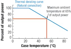
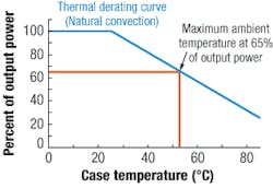
Let’s assume that we require 65 watts of output power from a 100-watt converteer with 90 percent average efficiency, a maximum temperature rating of 100 degrees Celsius based on worst-case semiconductor junction temperatures within the converter. It has a thermal impedance of 6.75°C per watt and the derating curve shown in the figure.
These curves are provided in several forms, but they are all governed by one key factor pertaining to the converter’s case: its temperature rise above ambient.
The figure shows percent of output power verses case temperature. The curve could be given in terms of output current as well. If the designer knows the system requirements in terms of maximum ambient temperature, he can determine the conversion factor by using its thermal impedance.
As the converter is rated to operate to 100°C, the maximum ambient temperature equals 100°C minus the converter’s rise above ambient (Pdiss × 6.75) or about 47.25°C. This gives 100 minus 47.25 or about 53°C. This is the free air (natural convection) max ambient temperature.
Now assume our maximum system ambient temperature spec is 75°C; this means the converter temperature must be reduced by 17°C (75°C - 53°C = 17°C) for the converter to operate at 100°C. Keep in mind general component derating. The converter is a component and should be derated from a temperature standpoint as well as from a power distribution standpoint.
Calculating the heat-sink properties required to reduce the case temperature by 17°C can be accomplished in the same manner. About 7 watts still must be dissipated, but the temperature rise must remain within 17°C.
The new thermal impedance required is 17°C per 7 watts = 2.5°C per watt. This means that the heat sink necessary to operate the converter at 65 watts out at an ambient temperature of 75°C must be capable of 2.5°C per watt maximum, including any junction impedance between the converter and the heat sink. Hence thermal interface materials such as grease or thermal pads are used.
Mounting considerations
Mobility means vibration, and long-term exposure to vibration can be catastrophic. To overcome the effect of vibration on converters, two major mounting factors should be considered. The first is the mounting of components within the converter. The second is mounting of the converter assembly and all of its associated external components and cabling.
In severe environments, encapsulation (potting) can benefit in three ways. It acts as a moisture barrier, it protects components from vibration, and carefully chosen potting disburses thermal energy from the components to the converter’s case.
When mounting the converter involves threaded inserts, it is best to adhere to the manufacturers torque guidelines. Over torquing may lead to stripped hardware and/or deformation of the mounting surface. Also, understanding the co-planarity and finish of the converter’s mounting surface will help in choosing the proper thermal interface material.
The mass of the converter influences its mounting requirements and resilience to vibration. Power designers are constantly looking for ways to reduce size. By and large a power converter’s largest components are the magnetics (transformers and inductors). The key element to reducing the size of the magnetics is the frequency of operation (Fsw).
As shown in Faraday’s law, B = (Ton×Vin×108/(Np×Ae), the flux density (B) is inversely proportional to the equivalent area of the core (Ae) and Fsw. The relationship between Fs and Ae provides the ability to raise the frequency while lowering the core size, thus maintaining the same flux density (B).
The extent to which this balance can be maintained is gated by factors like core material limitations, parasitics, and current carrying capability (size of the wire used).
The availability of increasingly compact magnetics and power semiconductors like field-effect transistors, transistors, and diodes has contributed to the reduction in package sizes. Consequently power sources, which in the past have been too cumbersome to effectively incorporate into vehicles and too inefficient to operate off of battery power, are now accessible to designers of mobile-vehicle-based systems.
Cabling and input-filter factors
It is important not to overlook converter source impedances. Consider a one-half brick converter (2.28 by 2.4 by 0.5 inches) designed to operate from 10- to 36-volts DC at 156 watts output at an efficiency of 87 percent.
With the input at low line (10-volts DC), the average input current is Pin/Vin or Pin = 156/0.87 = 179.3. The average input current then is 179.3/10 = 17.9 amps. From here the peak current can be calculated as I average/max duty cycle (0.7) = 17.9/0.7 = 25.6 amps.
If the battery is located in the rear of the vehicle and the system is located under the dashboard, it becomes difficult to maintain low source impedance because of the resistance and inductive effects of the cabling.
Consider the I2R drops for a 15-foot, 10-gauge cable. At about 1 ohm per 1000 feet, 15 feet of cable results in a resistance of 0.015 ohms. At worst case the average power dissipated in the cable alone equals 17.92 × 0.015 = 4.8 watts.
The deviation in input voltage due to the peak ripple currents and load transients at 10-volts DC input would be enough to trigger the undervoltage lockout (UVLO). The input voltage would rise to the point of turn on. As the converter delivered current to the load, the input current transient would cause the converter’s input voltage to dip below the undervoltage lockout, shutting the supply down. This will appear to be an oscillation to the user.
One solution is to add more hysteresis, or to slow down the UVLO. This has further consequences, however. Power increases by the square of the current. If the main switching field effect transistor has an rds on of 0.006 ohms, the Pdiss at a UVLO of 9.5 Vin = (18.842 × 0.006) × duty cycle = 2.1 × 0.7 = 1.5 watts.
If the input were allowed to run down to about 7.5-volts DC, the Pdiss = 3.14 × 0.7 = 2.4 watts. This is a lot of power to dissipate in such a small semiconductor package.
The real issue is the apparent high output impedance of the source. By increasing the cable size and terminating the input cabling with a large, low-ESR capacitor, the resulting storage capacity along with the reduced impedance of the cabling allows smooth operation through transients and low line operation.
DC-DC converters have a lot to offer in tightly regulated output voltages, efficiencies that make battery management feasible, and reduced size allowing an overall compact system design. Demand for devices demanding extremely low source voltages is growing. While using low input voltages is not a new technology, it raises strikingly different challenges than those exhibited by higher voltage sources.
Tim Powers is the Engineering Manager at Wall Industries Inc. in Exeter, N.H. He holds a B.S. degree in electrical engineering from Wentworth Institute of Technology; e-mail: [email protected]. Sean Penglase is a design engineer at Wall Industries. A graduate of Michigan Technological University, he holds an EET degree; e-mail: [email protected].

