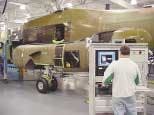
Ridley Park, Pa. — Engineers at Boeing Army Rotorcraft Systems in Ridley Park, Pa., wanted to save time and improve efficiency in their helicopter avionics. They began upgrading their existing manual test equipment with automated functional test procedures and an automated test system (ATS) four years ago with the help of In-Phase Technologies Inc. in Clarksburg, N.J. They have had success ever since.
The Boeing facility produces completed fuselages for MV-22 and CV-22 Osprey tiltrotor aircraft for the U.S. Marine Corps and U.S. Air Force Special Operations Command, respectively; CH-47 and MH-47 Chinook helicopters and Special Operations Chinooks; and, until a recent contract cancellation, RAH-66 Comanche armed reconnaissance helicopters for the U.S. Army.
The work with In-Phase resulted in a custom-designed automated coaxial cable test system that eliminated problems associated with the previous manual test procedures. "Actually, the first system was put to work on our Chinooks which are completed here on site," says Kathy Kocher, a Boeing test engineer. "The V-22 fuselages are completed here as well, but after testing they are shipped to another manufacturing facility for final assembly.
"Our new automated test systems are substantially more robust, and eliminate all of the previous variability problems as a result of operator discretion," Kocher says. "It is a much more stable platform now. There have been virtually no field failures of any coax cable runs that have been through the new ATS."
In addition to thousands of components that comprise an aircraft's fuselage, each shipset also incorporates scores of coaxial cables for avionics including communications, navigation, and aircraft protection systems. The coax cables, their connectors/terminations, and their antennas must be thoroughly tested for continuity, insertion loss, voltage standing wave ratio (VSWR), and other reliability and performance parameters.
These tests include — but are not limited to — phase delay, and "distance to fault" (when fault diagnostics are required) to point out cable discontinuities. These testing procedures had been time consuming and tedious. "On a good day a technician could test about five cables aboard a V-22, for example," Kocher says, and even then "we were usually disappointed with the test results."
More important, when completed aircraft were delivered to their military customers some of the electronic systems connected to the coaxial cables failed, which required expensive troubleshooting by Boeing engineers and technicians. Problems often revolved around the coaxial cable or connectors between the aircraft's power sources and several avionics systems.
"In the past, by the time our helicopters got to the customer and they started plugging in all the black boxes, there would be failures for many reasons," says Herman Richardson of the Manufacturing Engineer Test System (METS) Group for the Ospreys and Chinooks. "At times we experienced failures, and technicians replaced components but never considered troubleshooting or replacing cables and connectors." He also serves as a production and instructor pilot for the CH-47 Chinook
During this period Boeing was testing these cables individually, with scalar and vector network analyzers; essentially, manual testing that required complex pre-test set-up prior to a series of independent test procedures. The tests were solely to determine insertion loss and VSWR characteristics, and were based on minimum and maximum parameters — on virtually every cable run that incorporated coaxial connectors aboard the aircraft, company officials say.
Richardson adds that there was still no way for customers to know that what they are testing is correct, even when they tested the coaxial cable in the field and determined its conformance to specifications. "Even when they detect a good signal, when the cable is connected to its antenna and its receiver the performance loss is reduced by some degree to the point that, in a lot of cases, the system is not usable," he says.
"Once the aircraft is built they [the Army] do not necessarily go back and check insertion loss in the coaxial cables. That's what we are supposed to do here," Richardson says. In the field, the Army typically restricts testing to the "black box switching out from the antenna; therefore, they have no reason to think that the cable is bad.
"Even so when signal continuity appeared to be adequate there still may be electrical losses when system connections are completed, rendering some electronic systems unusable," Richardson continues. It was "frustrating trying to correct these problems, so that when I joined Boeing I figured out how we test these cables and that we needed to do something differently."
The automated test system (ATS) not only performs qualitative functions (basically go/no-go testing), but also provides complete statistical data and documentation with regard to precise performance parameters such as insertion loss, frequency roll off, and distance to fault, company officials say.
The system also provides an internal confidence test routine, an internal path loss calibration routine, and uses pictograms for instructing test operators in connecting cables, detectors, and standards. For distance to fault incidences, the system prompts for propagation factor for the various cable dielectrics.
During cable measurement, the system can also be configured for statistical process control functions by archiving all test data into a permanent database. Measurement results can also be displayed in graphs, table format, or both.
The automated coaxial cable test system at Boeing Vertol consists of an Anritsu Scalar Network Analyzer (SNA) and a PC with custom developed measurement software. The computer controlled SNA measures insertion loss and/or VSWR of every coaxial cable within an aircraft. In addition, an available option can be provided to measure distance to fault for any cable that is found to be defective.
The SNA incorporates two sensors and an autotester, which is basically a directional bridge and sensor integrated into a single package. The SNA also has a self-contained signal generator that supplies the RF/microwave stimulus required for the tests.
For more information on In-Phase Technologies contact the company by email at [email protected] or online at www.in-phasetech.com.


