By Tom Adams
The Restriction of Hazardous Substances (RoHS) legislation that has led to an essentially global ban on the use of solders containing lead in electronics production, permitted exemptions for military, aerospace, and a few other users who still needed to use leaded solders. After a brief interval, component manufacturers converted virtually all of their components to lead-free solders such as Tin-Silver-Copper SAC, leaving those with exemptions with no source for components for tin-lead solder.
The need for these components gave impetus to a niche industry whose business was using hot solder dipping to remove the pure tin finish from the component terminations, and refinishing the finish with tin-lead solder. One basic requirement is that all of the pure tin must be removed to avoid tin whisker growth. To do this, the component’s terminations must be dipped in hot tin-lead solder right up to the body of the component.
Dipping means that the body of the part may be thermally stressed. The whole operation–fluxing, dipping, and cleaning–needs to be precisely controlled because it is easy to cause internal damage to the component.
If the external terminations become too hot for too long, heat transferred into the body can cause lead fingers to delaminate from the mold compound, setting the stage for a future electrical failure. The heat may also cause a crack in the mold compound itself. The duration of the hot solder dip needs to be precise, and the immersion depth of the terminations also needs to be precise. Leaving even a small band of the original pure tin solder on a termination opens the way for tin whisker growth during service.
Within the niche industry there are companies that use robotic methods, partly automated methods, and largely manual methods. Standards of some sort were necessary to give the solder refinishers and their customers’ guidance for finish replacement.
The Information Technology Association of America (ITAA) has completed GEIA-STD-0006, “Requirements for Using Solder Dip to Replace the Finish on Electronic Piece Parts.” The standard lays down definitions for equipment, tools, materials, processes, and documentation. “It provides a method for people that still want to use tin-lead to convert their parts from lead-free to tin-lead for their applications,” explains Steve Martell of micro imaging specialist Sonoscan Inc. in Elk Grove Village, Ill., and advisor to the committee that wrote the standard.
“It gives some guidelines on the kinds of things they need to be aware of or concerned about that could be a problem when they do that type of termination finish change,” Martell says. He points out that changing the finish on the leads voids the warranty given by the manufacturer of the component. The voiding of the warranty makes it essential that the company replacing the solder do no damage to the components.
The standard requires nondestructive acoustic micro imaging to photograph internal features in the components before and after hot solder dipping. The standard refers to the accept/reject criteria in Section 6 of J-STD-020D (Moisture/Reflow Sensitivity Classification for Non-hermetic Solid State Surface Mount Devices), but also includes criteria specific to hot solder dipping. For one thing, it defines the acceptable expansion in size of a delamination at an internal interface. A die attach delamination, for example, is permitted to expand by no more than 10 percent of the total die attach area.
Compliance with Standard 0006 is voluntary, Martell notes, but the standard tells everyone involved how to avoid damage to components. “If it’s an end user that already has the parts, it gives them information about how to change the termination finish without causing damage to the parts,” Martell says. “If it’s a distributor that’s trying to supply parts to the military or someone else looking for tin-lead, then the purchase order they get from their customer may specify to do the termination finish changes according to 0006.”
Don Tyler is vice president of Corfin Industries LLC in Salem, N.H., which specializes in robotic hot solder dipping. The standard, he explains, is in a sense related to the TMTI (Transformational Manufacturing Technology Initiative) program developed earlier by the Navy. Tyler explains that TMTI “was a study that was done with a wide variety of package constructions of parts that had lead-free alloys on them, and the goal was to flush it all off with tin-lead using robotic hot solder dip, and prove that it always did the job and that it wouldn’t damage the parts.” “So those particular parameters, which are temperatures, dwells, dip depths, and tolerances of those values, are always maintained for products as well,” he says.
Most of the components that come into Tyler’s shop have pure tin finishes, but some have conventional tin-lead finishes. Some of the components may have been stored in environments that degraded the tin-lead finish. Others were removed from boards. Others simply have a tin-lead finish that is much more porous–and hence less durable–than the finish that Tyler puts on.
A component coming into Tyler’s shop is inspected and, if necessary, baked per J-STD-033. After preparation, vacuum grippers or titanium tweezers pick up the component by the body and move it to a flowing bath of flux. “It’s a pumped flux wave,” he says, “and as that flux is consumed in the process, or as the thinner evaporates, flux or thinner is pumped in to maintain that same activity level, the same specific gravity value. So it’s consistent throughout the process.”
The terminations of the component are dipped in the flux. Excess flux is then blown off by air, and a forced hot-air pre-heater activates the flux and dehydrates it.
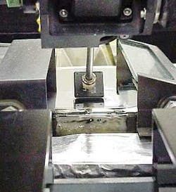
The component then goes to a dynamic soldering wave. “We use Sn63 here,” Tyler notes. “Other alloys will work as well, but for the purposes of what we’re talking about we’re using Sn63Pb37, under a nitrogen blanket. There are 300 pounds of solder there, flowing. So the length of the terminations is dipped into the solder, up to the edge of the body.”
This is where precision really matters. The arm holding the component needs to dip it deeply enough to cover the entire length of the terminations, but not so deeply that excess heat will create internal damage within the body of the component. The machine that carries out the hot solder dipping controls the temperature, the dipping level, and the duration of the dip–and costs around half a million dollars.
The purpose of the Navy study that preceded 0006, Tyler says, was “to make sure that there was no way you could avoid contact with the edge of the body if you were going to do the job of flushing everything on the termination off. And so the goal was to verify that, in fact, it was not damaging the part.
“So by having the robotic control of tight tolerance on the dipping depth as well as the temperature and the dwell, we were able to ensure that damage didn’t occur to the body, yet it was doing the job of flushing off all of the alloy on the length of the leads,” Tyler explains.
After robotic hot solder dipping (RHSD), the component cools for a brief period, and then goes into an ultra-filtered hot water wash. The component is moved back and forth in the wash, as fresh water continuously pours in. At the end of the cycle, all of the water is replaced to avoid contamination.
The robotic process controls the time of each procedure carefully. Standard 0006 does the same, specifying, for example, that the time that each side of a component remains in the hot solder dip must not exceed 5 seconds.
Another critical parameter is the interval between hot solder dipping and hot water cleaning. Long delays, which can occur when manually dipped parts accumulate for later mass cleaning, mean that the flux will solidify and become much harder to clean off. In that case, there is a good chance that the cleaning process will leave some flux behind. Standard 0006 requires cleaning to occur within one hour after hot solder dipping. Corfin’s robotic process moves components to the hot water cleaning within 5 to 10 seconds after dipping. The precise interval depends on the part type, but is just long enough to permit the component to cool down to the temperature of the hot water wash. Standard 0006 requires that the “temperature of the cleaning process shall be within ±10 °C of the qualification profile.”
After the hot-water wash, some or all of the parts are inspected by acoustic micro imaging to ensure that no internal damage has occurred during the replacement process. For qualifying a lot of parts, 100 percent of the parts are inspected. For routine production, a small sample of parts is examined.
At this stage, Martell explains, acoustic inspection “provides the nondestructive assurance of quality, and shows that the parts have not been compromised, even though the termination finish has been modified. You want to know that the parts will perform as they did before modification.”
Like the hot solder dipping itself, the acoustic inspection can be either manual or automatic. Relatively small numbers of components are easily inspected by a laboratory-style acoustic microscope. Larger numbers are more conveniently inspected by automated systems that carry the parts in JEDEC-style trays, perform automated acoustic imaging, and report the results for each part.
The standard for replacing the finish on terminations should make it easier to use components having tin-lead finish in critical applications, such as missile systems, where an electronics system may remain unpowered and in storage for years. By providing consistency in the methods that replace the finish, the standard should simplify the job of maintaining supplies of legacy components over the long term.
Correction:
The November 2008 print edition of Military & Aerospace Electronics incorrectly reported expected changes in defense spending, as predicted by the Government Electronics Industry Association (GEIA) segment of the Information Technology Association of America in Arlington, Va.
From 2019 to 2019, the GEIA expects U.S. military spending for operations and maintenance to increase from $167.92 billion to $229.1 billion; for research, development, test, and evaluation (RDT&E) to decrease from $78.1 billion to $55.54 billion; and for procurement to increase slightly from $101.15 billion to $102.53 billion.
These numbers reflect the GEIA’s base-budget forecast in constant-year dollars, which does not account for projected inflation.
Military & Aerospace Electronics regrets the error.


