By Tom Adams & Keith Gurnett
Video cameras and digital cameras (including those in cell phones) virtually all use CMOS image sensors, which entered production about 20 years ago. In that time, the technology has experienced numerous advances. Now, however, CMOS image sensors are beginning a qualitative change that will provide a stunning range of new products for consumers, as well as for military and aerospace users.
Going to the backside
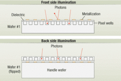
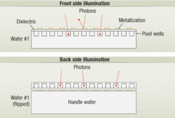
The technological revolution involves a basically simple idea: the sensor chip is flipped over to increase performance. In its conventional form—which includes all or nearly all of the digital imaging technology currently in production—the CMOS image sensor is a semiconductor chip having millions of tiny pixel wells. A pixel well is simply a defined area where photons that strike the sensor pass through silicon and strike a junction, where each photon creates an electrical signal. The electrical signals are read and processed to make the image. (It takes several pixel wells—anywhere from 4 to 81 or more—to make one pixel in the final displayed image.)
In conventional image sensors, the metallized circuitry of the chip lies above the pixel wells; the metallization, however, can cause problems by reflecting or refracting a considerable portion of the incoming light. Less light enters the pixel wells, and the result is a less efficient image sensor. Designers try to shrink the frontside metallization to allow more photons to reach the pixel wells, but the advantages to be gained are not great.
The new CMOS image sensors, which are nearing production, solve this problem in the following manner. First, an unpatterned silicon wafer—the “handle” wafer—is bonded to the face of the wafer on which the pixel wells and the metallization have been patterned. The unpatterned wafer of course blocks any light at all from reaching the pixels wells via the conventional route.
At this stage, however, the pair of bonded wafers is flipped over, and chemical-mechanical polishing removes nearly all of the thickness of the pixel well wafer. After polishing, the remaining silicon that overlies the pixel wells is only about 20 microns thick, and the layers of metallization lie beneath the pixel wells. This technique, called backside illumination, greatly increases the efficiency of the CMOS image sensor because the circuitry no longer blocks incoming photons. It also explains why the handle wafer is necessary: if the pixel wells wafer were thinned down to 20 microns by itself, it would be very flexible and impossible to handle without damage. (It would also be optically translucent, and would look red if held up to a light source.)
Backside thinning makes it possible to fill the pixel wells with photons quickly and completely so that they have a very high signal-to-noise ratio. The patterning and metallization of the pixel wafer, the bonding with the handle wafer, and the thinning of the pixel wafer are all done at the wafer levels. After the wafers are bonded, they are diced into individual image sensors.
Key parts of the system
The completed CMOS imaging system has four key parts: the pixel wells along with the interconnects for rows and columns, analog-to-digital (A/D) converters to change the analog signal into digital, digital signal processing (DSP) circuitry to read the signals coming from the pixel wells, and a screen or other display. In some of the designs now being proposed, the DSP circuitry is part of the metallization on the pixel wells chip.
In current digital cameras and cell phones, the DSP function is handled by a separate chip, an arrangement that slows processing by adding to the distance that electrical signals must travel along wires. A separate DSP chip also increases the amount of real estate needed for the overall sensor system.
The conventional size for digital image chips is one-quarter inch, measured diagonally. Putting all functions except display onto a very thin chip stack of this size saves valuable space. It also means that the sensor manufacturer can get hundreds or thousands of sensors out of a single bonded wafer pair.
Competition heats up
Several companies are in a heated competition to become the first to market the new backside illumination CMOS image sensors. The companies include Sony, ST Micro, and OmniVision. The approach of each company depends on the intended applications.
Toshiba, for example, is shunning backside illumination and sticking with frontside illumination, counting on optimization of the current technology to allow them to bring consumer products to market more quickly and at lower cost, in part because only a single wafer is involved. But Toshiba is targeting consumer markets, and is probably less likely to have CMOS image sensors that would be attractive to military or aerospace users.
Wafer preparation and bonding
At least initially, backside illuminated CMOS sensors will be more expensive than conventional frontside sensors. Part of the added cost comes from the need to bond the two wafers—a process that is not trivial. The two wafers first have to be prepared for bonding.
The preparation process includes plasma activation, which is designed to increase the bond strength. It prepares the surface so that the reactive chemical species that are on the surface will react with the second wafer and create a bond.
After plasma activation, the wafers are very meticulously cleaned to remove any possible contaminants such as sub-micron-sized silicon particles. The preparation of the two wafers for bonding is very critical and needs to be carried out in an ultra-clean environment because even a small number of airborne particles less than 1 micron in diameter can cause considerable damage by preventing the wafers from bonding.
Bonding of the wafers and subsequent thinning of the pixel wells wafer down to 20 microns all add cost, but the developers of the advanced CMOS image sensors are betting that the greatly improved performance will outweigh the initially higher prices. The production goal is to create the image sensors on the largest feasible wafers—8-inch, or even 12-inch—and achieve very high yield, so that each bonded wafer pair can be diced into the largest possible number of usable image sensors.
The two wafers are then aligned very precisely and the two prepared surfaces are brought together. At a touch point along the edge, the two wafers are momentarily pressed together, and a bonding wave moves across the interface. The wafers are now well bonded. And annealing step makes the bond even stronger.
Other variations on the technology are possible. If a very high-performance sensor system is needed, it might be advantageous to place the digital signal processing circuitry on a separate wafer. This would mean that the pixel wells wafer would be connected to the DSP wafer by through-silicon vias running through the handle wafer. Such a system would require two bonding operations to bring the three wafers together, and would be even more expensive, but for some applications the cost might be justified.
The technological race is to bring the CMOS imager and turn it into a camera with outputs to some sort of logic. You can’t bond another wafer to the face of the chip. You need to have the camera exposed—you can’t put something on the face of it because it will block your view. So the process has got to be developed to make it be a 3-level wafer stack, and the handle wafer may become a sort of interposer leading to the third wafer.
Pixel well sizes are critical
One of the big advantages of backside illumination is the opportunity to shrink the size of the individual pixel wells in the pixel array. Current technology uses pixel wells that are typically around 2 microns by 2 microns. ST Micro, for example, makes a CMOS image sensor that has an array of 1,600 by 1,200 (2 megapixels) 1.75 micron pixels. Shrinking pixels using frontside illumination faced severe limitations, but backside illumination makes shrinking the pixel wells much easier.
Likely next steps over the next few years are pixel well sizes down to about 1.1 microns, and then below 1.0 micron. As the area of each pixel well shrinks, the number of pixel wells that can be packed into an array of a given size increases rapidly.
The rate of shrinkage is proceeding at about the same rate as the reduction in semiconductor feature sizes predicted by Moore’s Law.
One estimate is that by cutting pixel well size in half—from 2 microns to 1 micron—that number of pixel wells will increase by a factor of four without changing the size of the image sensor. Same sensor size, similar cost, but much higher resolution.
Pixel well size, however, does not tell the whole story. Consumers are conditioned to equate a higher well pixel count with superior performance, and within limits this is an accurate assumption. But in some applications, and especially where light is dim and it is important to achieve the highest possible signal-to-noise ratio, larger pixel wells using backside illumination would be an excellent solution.
Consumer digital cameras typically are for bright-light situations, or achieve bright light by using flash. They will be able to take advantage of pixel well sizes down to 1 micron and below. In many applications, military cameras will be able to take advantage of the same pixel well sizes because enough light is available.
The military will also want to use backside illumination for cameras in dim light situations, where the pixel well size might be 5 or even 10 microns to capture the highest possible number of photons and maintain a very favorable signal-to-noise ratio. Night-vision systems, long in use by the military, use infrared light that requires a different technology.
Military and aerospace applications
Military and aerospace applications can be expected to take advantage of backside illumination in both the small-pixel and large-pixel arenas. Nixon O, technical director at Dalsa Corp. in Montreal explains the potential allure of small pixel wells. “Where I think you would see the push to backside thinning in the military is in applications where they simply can’t tolerate the larger size, probably more than cost. The size of the power constraint is that they just can’t go above a certain size and they still want to have the high resolution, so they’re forced into smaller pixels, and to get every photon that they possibly can at that point they would move to backside thinning.”
Such cameras would probably be small in size, would use small lenses, and would be relatively inexpensive—much like the cell phone cameras that are the primary drivers of backside illumination. If what is needed is surveillance of a perimeter, for example, it might be feasible to deploy hundreds or even thousands of cameras at selected locations. The cameras will be tiny, consisting of a very small pixel array, DSP circuitry, and a means to transmit the image to a central location.
The cameras should be relatively inexpensive, in part because the demand for high-performance cell phone cameras will drive manufacturers to fine-tune the production processes needed to put thousands of sensors on a wafer. If the size of the individual sensor chip is one-quarter inch by one-quarter inch, then a 12-inch wafer can yield over 1,000 sensors. The proposed 18-inch wafers might yield close to 3,000 sensors.
Large-pixel cameras that take advantage of backside thinning could play vital roles, especially in dim-light situations.
Dalsa already makes large-pixel sensors for DNA sequencing fluoroscopy, where it is essential to capture as many photons as possible with a very high signal-to-noise ratio.
“If you want to get the very best noise performance,” Nixon O explains, “then you want to aim for larger pixels.” Similar cameras are used in astronomy; backside illumination versions of these cameras might have use in aerospace applications.
Pixel well size to some extent determines the dimensions of the pixel array and the dimensions of the lens that is needed. Many small-pixel military applications would probably use lenses like the tiny lenses in cell phone cameras. But a large-pixel camera designed for high performance in very dim light in an application where weight and size are not critical might use a lens up to three inches in diameter.
The first of the new backside-illumination CMOS image sensors should be available from manufacturers sometime during the next twelve months. Their improved photon-collection capabilities, along with shrinking pixel well sizes, will create interesting competition among the key players. As production costs come down, a new generation of digital cameras will be available to meet military and aerospace requirements.


