Reducing EMC qualification risk in aerospace and defense electronics
Key Highlights
- Early EMC analysis and failure signature documentation are crucial to prevent costly redesigns and schedule delays.
- Identifying the source, coupling path, and affected function helps target corrective actions effectively.
- Controlled modifications, such as shielding improvements or cable routing changes, validate hypotheses about EMC failures.
- Understanding the relationship between system interfaces and electromagnetic behavior is vital for aerospace and defense applications.
- Pre-compliance testing should mimic actual installation conditions to ensure the effectiveness of fixes and reduce qualification risks.
LAVAL, Quebec - Electromagnetic compatibility failures remain common even in mature electronics development. Intertek has reported initial EMC failure rates of approximately 50%, and Tektronix continues to cite a similar first-pass failure rate when pre-compliance testing is not considered.[1][2] These figures are general industry data rather than military- or aerospace-specific statistics, but they illustrate an important point: formal qualification should not be the first time a design's electromagnetic behavior is seriously investigated.
The consequences can be greater in aerospace and defense programs. A late EMC problem may affect not only a PCB, but also an enclosure, harness, connector, grounding scheme, antenna installation or system interface. The cost is therefore not limited to another laboratory session; it can include redesign, configuration-control changes, repeated qualification work and schedule impact.
The key is to turn a failure into engineering evidence.
|
Failure signature -> source and path -> targeted correction -> verification |
![Figure 1. General-industry first-attempt EMC outcome used as context; the approximately 50% figure is not military/aerospace-specific. Sources: Intertek Testing Services NA and Tektronix.[1][2]](https://img.militaryaerospace.com/files/base/ebm/mae/image/2026/08/6a8f45354a9fbd3205175f32-figure_1_first_pass_emc.png?auto=format,compress&fit=max&q=45?w=250&width=250)
Qualification tells you what failed - not necessarily why
Military and aerospace programs commonly address EMC at more than one level. MIL-STD-461 establishes emission and susceptibility requirements and verification methods for equipment and subsystems, while MIL-STD-464 addresses electromagnetic environmental effects at the system level.[3][4] For airborne equipment, RTCA DO-160 is also widely used for environmental qualification, including electromagnetic test categories.[5]
Passing an equipment-level test, however, does not eliminate every integration risk.
The electromagnetic configuration can change when equipment is installed: cable length and routing change; shield terminations and structural bonds change; the enclosure is connected to a platform; nearby transmitters and antennas appear; and power and return-current paths change.
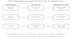
An EMC problem is therefore more usefully viewed as a relationship between three elements: source, coupling path, and affected function or radiating structure.
The source might be a processor clock, switching converter or RF transmitter. The path might be PCB coupling, common-mode cable current or an enclosure discontinuity. The observable result might be a radiated-emissions exceedance, receiver degradation, sensor disturbance or processor reset. A correction is much more defensible when the engineer knows which part of this chain it changes.
Start with the failure signature
The first step after a failed test should be to preserve the information contained in the failure. Suppose radiated emissions exceed a limit at several narrow frequencies. Before changing the hardware, determine whether those frequencies correlate with known clocks, switching frequencies, communication interfaces or RF activity.
Operating state can be equally informative. Does the emission increase when a transmitter is enabled? Does it disappear when a subsystem is disabled? Does moving a cable change the amplitude? Does the frequency move when a switching frequency changes?
For an immunity failure, the same principle applies. Record the applied frequency and level, the exact failure mode, operating state and the first internal function that becomes abnormal.
· What frequency or condition produces the failure?
· Which operating state changes it?
· Which physical configuration changes it?
· Which subsystem has a plausible relationship to that signature?
This narrows the investigation before redesign begins.
Localize the source and coupling path
Once the signature is understood, diagnostic measurements can separate the original noise source from the structure that actually couples or radiates the energy. Tektronix describes a practical troubleshooting sequence using near-field probing to identify candidate sources, a current probe to measure high-frequency cable currents, and an antenna measurement to determine which components actually radiate.[7]
This distinction matters. A processor may generate high-frequency energy without being the dominant radiator. That energy may couple onto an I/O cable, and the cable may become the efficient radiating structure. Rohde & Schwarz likewise documents common-mode current on connected cables as an important radiated-emissions mechanism.[8]
Consider a narrowband radiated-emissions failure at a harmonic of a digital clock. If a near-field probe identifies strong energy near the processor and connector, a current probe shows the same harmonic on an external cable, and the far-field measurement contains that frequency, the evidence supports a specific mechanism:
digital source -> common-mode cable current -> cable radiation
That is more actionable than simply knowing that the product exceeded a limit at one frequency.
Use controlled changes to test the hypothesis
Troubleshooting becomes less reliable when several modifications are applied simultaneously. A better approach is to make controlled temporary changes that test one suspected mechanism.
Examples include temporarily improving a shield connection, adding common-mode impedance to a cable, bridging an enclosure seam, changing cable routing, changing a converter frequency, or disabling a suspected subsystem. These are diagnostic experiments, not automatically the final production solution.
If temporary common-mode impedance substantially reduces a failing emission, the result strengthens the hypothesis that cable current is part of the radiating mechanism. The final correction might instead be better connector bonding, filtering, PCB return-path control or cable architecture.
The important point is cause and effect: a modification should change the measured signature in the direction predicted by the hypothesis.
Susceptibility failures require the same method
A system reset during radiated susceptibility testing is a symptom, not a root cause. RF energy may couple through an external cable, enclosure aperture, power connection, shield or grounding structure. It may then disturb a power rail, reset circuit, communication interface, analog front end or sensor.
The troubleshooting question should therefore change from "How do we stop the reset?" to "How is the disturbance reaching the circuit that resets?"
Monitoring internal rails, reset signals, communications and sensitive analog nodes while controlling suspected coupling paths can expose the mechanism. A correction based on an identified mechanism is more likely to remain effective when the system configuration changes.
Integration can change a successful fix
Aerospace EMC performance depends strongly on interfaces. NASA's grounding guidance treats spacecraft grounding architecture as a system design issue and discusses interactions among intentional RF sources, switching electronics and grounding relationships.[6]
Bonding, shielding, cable architecture and enclosure design therefore cannot always be evaluated independently. A cable shield may perform well only if it is terminated correctly at the equipment boundary. A filter may be technically suitable but ineffective if physical layout allows high-frequency coupling around it. A conductive enclosure may lose shielding effectiveness at seams, connectors or penetrations.
For that reason, pre-qualification verification should reproduce the intended installed configuration as closely as practical, particularly for cables and harnesses, connector backshells, shield terminations, grounding and bonding, representative loads, and operating modes. A fix validated only in an artificial bench configuration may fail again after installation.
Pre-compliance should answer engineering questions
Pre-compliance testing provides the most value when it is used for diagnosis and margin assessment - not merely as an inexpensive imitation of formal qualification.
1. Capture the baseline. Document configuration, operating mode, and the frequencies or conditions of concern.
2. Correlate the signature. Compare the failure with clocks, converters, RF activity, interfaces, and subsystem states.
3. Localize source and path. Use near-field measurements, cable-current measurements, monitoring, and controlled configuration changes.
4. Apply a targeted correction. Change the mechanism most strongly supported by the evidence.
5. Verify the correction locally. Confirm that the expected signature changes.
6. Return to the broader test configuration. Check that the correction remains effective across relevant frequencies, modes, and interfaces.
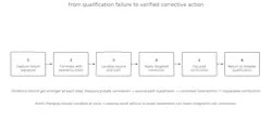
This process is more efficient than repeatedly modifying the design without knowing which mechanism is dominant.
Do not design for a bare pass
A result just below a limit may technically pass but still indicate qualification risk. Production tolerances, component substitutions, cable placement, software states and installation details can shift EMC behavior. Development testing should therefore identify not only failures, but also areas with limited margin.
The amount of margin required depends on the program, requirement and measurement uncertainty. There is no universal number. The engineering objective is simpler: know where the design is sensitive before formal qualification discovers it.
From a failed test to a defensible correction
Not every EMC failure can be predicted. Aerospace and defense electronics combine too many sources, interfaces and operating conditions for that. What can be controlled is the engineering response.
A useful EMC investigation converts a test failure into a measurable signature, a source/path hypothesis, a controlled experiment, a corrective action and a verification result. That changes qualification from a repetitive pass/fail exercise into a source of engineering information.
The strongest result is therefore not simply that the equipment passes its next test. It is that the engineering team understands why it passes and has evidence that the corrective action addresses the actual electromagnetic mechanism.
About the author
Reza Khalvandi is an engineer with Stancer Testing-Lab in Laval, Quebec, Canada. His work includes technical development and engineering initiatives related to EMC/RF testing, pre-compliance, and product troubleshooting.
References
[1] Intertek Testing Services NA, Inc., 'Why 50% of Products Fail EMC Testing the First Time.' Intertek white paper; archived copies remain widely cited in EMC literature.
[2] Tektronix, 'EMI/EMC Testing: Equipment, Procedures & Setup.' Tektronix currently states that roughly 50% of products pass the first compliance attempt when pre-compliance is not considered. https://www.tek.com/en/solutions/application/emi-emc-testing
[3] U.S. Department of Defense, MIL-STD-461G, 'Requirements for the Control of Electromagnetic Interference Characteristics of Subsystems and Equipment.' Defense Logistics Agency ASSIST/Quick Search.
[4] U.S. Department of Defense, MIL-STD-464D, 'Electromagnetic Environmental Effects Requirements for Systems.' Defense Logistics Agency ASSIST/Quick Search.
[5] Federal Aviation Administration, AC 21-16G, 'RTCA Document DO-160 versions D, E, F, and G, Environmental Conditions and Test Procedures for Airborne Equipment.'
[6] NASA, NASA-HDBK-4001A, 'Electrical Grounding Architecture for Uncrewed Spacecraft,' Revision A, July 2025. https://standards.nasa.gov/standard/NASA/NASA-HDBK-4001
[7] Tektronix, 'EMI Pre-Compliance Testing and Troubleshooting with Tektronix EMCVu.' Application Note. https://www.tek.com/en/documents/application-note/emi-pre-compliance-testing-and-troubleshooting-tektronix-emcvu
[8] Rohde & Schwarz, 'EMI Debugging with Oscilloscopes,' Application Note 1TD05, Version 1.2e, August 2021. https://scdn.rohde-schwarz.com/ur/pws/dl_downloads/dl_application/application_notes/1td05/1TD05-12e_-_EMI_Debugging_with_Oscilloscopes.pdf