Is thermal management up to the high-performance computing challenge?
NASHUA, N.H. - The byproduct of waste heat is the scourge of high-performance embedded computing; the faster the processors, the more heat they produce, and the more difficult it can be for systems designers to keep their designs within temperature limits to avoid compromising performance.
Unfortunately, it’s a vicious cycle. Those who specify processing for demanding systems like electronic warfare (EW), surveillance and reconnaissance, image processing, and artificial intelligence continually want more capability. There’s no end in sight to the need to remove ever-increasing amounts of waste heat from powerful processing.
Fortunately there are solutions for today’s electronics cooling and thermal management challenges that range from conduction cooling, to forced-air cooling, to hybrid implementations of forced-air and conduction cooling, and finally to liquid cooling. Many of today’s thermal design decisions hinge on specific applications and projections for system and growth and upgrades. Embedded computing designers have adequate tools at their disposal — at least for now.
Thermal management issues
Embedded computing power has been increasing at a dizzying pace over at least the past decade, which complicates efforts to keep electronics cool. “Ten years ago we started with Intel server-class processors that dissipated about 60 Watts per processor,” explains Michael Shorey, director of mechanical engineer at Mercury Systems in Andover, Mass.
“Then Sandy Bridge [second-generation Intel Core i7, i5, and i3 microprocessors], which was 70 Watts per processor,” Shorey continues. “The Xeon processorThe escalating design problem doesn’t just involve waste heat, but also includes the growing size of powerful microprocessors, which can complicate efforts to reduce size, weight, and power consumption (SWaP). “It’s a big jump, not just in thermal power, but also in the real-estate on the card,” says Shaun McQuaid, director of product management at Mercury Systems. “Thermal solutions tends to grow with it.”
Further complicating the picture are the shrinking sizes of embedded computing enclosures and backplanes, coupled with the growing size and power of the processing components inside. “Think of an ATR box, a conduction-cooled vehicle-mount box, or avionics box with flow-though cooling, with modules inside,” says Chris Ciufo, chief technology officer of General Micro Systems (GMS) in Rancho Cucamonga, Calif.
“They just keep adding more horsepower, or the system needs more FPGAs [field-programmable gate arrays] and GPGPUs for artificial intelligence, and we just keep putting more and more in this ATR box and the things get hotter and hotter,” Ciufo says. “At some point, something’s got to give. How do we get the heat out of these high-density systems? There’s got to be a better way.”
Demand is growing for artificial intelligence capability, which necessitates ever-more-powerful processors. “Demand for smaller systems that do more continues to grow,” echoes Kevin Griffin, senior mechanical engineer at embedded computing chassis specialist Atrenne Computing Solutions, a Celestica company in Brockton, Mass. “Our customers are coming to us for new system designs and legacy upgrades with increased performance needs and want them to be smaller, lighter, and support increased heat loads. Power density is a major factor to consider when designing a system. As systems’ physical sizes are reduced and compute power increases, there is less mass that can be utilized to sink and remove heat. The power density keeps increasing as SWaP requirements continue. This trend is expected to continue into the foreseeable future.”
There’s no end in sight for these trends. “The challenge is that power density just keeps escalating, with fewer slots, and the ability to package and do things in fewer boards, and it is a challenger to dissipate that heat in smaller enclosures,” says Ram Rajan, senior vice president for engineering, research, and development at embedded computing chassis designer Elma Electronic in Fremont, Calif.
Thermal challenges will be there, and power densities continue to rise, agrees Ivan Straznicky, chief technology officer of advanced packaging at the Curtiss-Wright Corp. Defense Solutions division in Ashburn, Va. “Most of the really high-power digital electronics are sensor-processing modules with FPGAs and GPGPUs, and other really hot chips.”
Conduction cooling
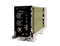
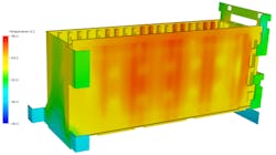
So what is an electronics thermal management designer to do? Solutions vary from traditional to the exotic. For aerospace and defense embedded computing applications designers typically start with conduction cooling, or channeling heat to the sides of circuit cards out of the enclosure through the enclosure’s walls. Designers sometimes blend pure conduction cooling and forced-air cooling to increase heat removal from the chassis.
Many of the company’s conduction-cooled designs involve the GMS patent-pending RuggedCool technology that enables systems using Intel-based microprocessors with a maximum junction temperature of 105 degrees Celsius to operate in an industrial temperature environment of -40 to 85 C at full operational load without throttling the microprocessor. Throttling refers to a processor that reduces its capability as it reaches its maximum operating temperature.
Instead of using thermal gap pads to conduct heat from the microprocessor to the system’s interface to a cold plate, RuggedCool uses a corrugated alloy slug with an extremely low thermal resistance to act as a heat spreader at the processor die. Once heat spreads over a large area, a liquid silver compound in a sealed chamber transfers the heat from the spreader to the system enclosure. “We can use Intel Core i7 processors without throttling,” Ciufo says.
GMS is moving to a second generation of RuggedCool technology to remove even more heat. “We had a seventh-generation Intel Core i7 processor, which was so hot that first-gen RuggedCool could not cool it at the 85 C limit without throttling it. Rugged Cool 2 solves that.”
This approach repurposes a thermal-management approach that GMS developed previously for high-performance VME embedded computing systems called Floating Wedgelock. “The typical wedgelock contacts the chassis in only two of three dimensions,” Ciufo says. “Our Rugged Cool 2 contacts it on three surfaces.” GMS is making RuggedCool technology available for industry-standard Modular Open Systems Approach (MOSA) and Sensor Open Systems Architecture (SOSA) designs.
Heat sinks
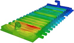
Often an important component of conduction are heat sinks, which are passive heat exchanger that transfers heat from microprocessors or other hot electronicConduction-cooled embedded chassis can have specially designed heat sinks that are part of or on top of chassis walls to speed heat removal once wedgelocks, heat pipes, or other thermal channels move heat off of circuit boards and to outside chassis walls. Designing the right kind of heat sink that fits into compact spaces and removes a great deal of heat can be a major design challenge.
Heat pipes
Related to conduction cooling are heat pipes, which use sealed liquid like water to transfer heat from hot spots in embedded computing systems, such as high-performance microprocessors by using thermal conductivity and phase transition. At the hot interface of a heat pipe, the liquid essentially boils and turns to vapor as it absorbs heat from that surface. The vapor then travels along the heat pipe to the other end near a cold interface and condenses back into a liquid, releasing its heat. The liquid then returns to the hot interface through either capillary action, centrifugal force, or gravity and the cycle repeats.
“We use heat pipes where the heat sink on the chassis or the air flowing over the chassis is insufficient,” Ciufo explains. “Heat pipes use vapor phase exchanges to remove heat. We have worked with heat pipe suppliers to buy a degree or two of cooling.”
Elma chassis designers also rely on heat pipes in conduction-cooled architectures when necessary. “Heat pipes are fairly common,” says Robert Martin, mechanical engineering manager at Elma Electronic. “We use them in applications where we need to distribute the heat load in conduction cooling to a cold plate. We also use them in commercial applications. Our largest competitive advantage is our ability to customize solutions, and we can suggest custom heat sink solutions, different materials like copper, and heat pipe solutions.”
Heat pipes are particularly effective in designs with intensely hot point loads — especially in small-form-factor embedded computing systems like 3U VPX, which pack a lot of computing performance into a small, hot space. “We have several pure conduction-cooled systems, and there the heat sink becomes very critical,” says Elma’s Rajan.
Convection cooling
Convection cooling is similar to conduction cooling, but uses fan-driven air flow to enhance cooling. PC and laptop computers typically cool internal hot components by exhausting hot air out of the computer using fans.
Convection cooling, however, can have several drawbacks in aerospace and defense electronic systems. First, it can introduce contaminants like dust and dirt that can damage sensitive components and interconnects. Second, raised circuit boards and raised components on the boards can partially block air flow and compromise cooling.
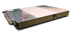
To overcome problems like these, military embedded systems designers often combine conduction and convection cooling to get the best of both worlds. The VITA Open Standards and Open Markets trade organization in Oklahoma City offers two standard design approaches that combine conduction and convection cooling in the popular OpenVPX embedded computing form factor: VITA 47.7 Air Flow-By cooling, and VITA 47.8 Air Flow-Through cooling.
“Air Flow-Through is gaining more acceptance because it is less complicated than liquid cooling,” says Curtiss-Wright’s Straznicky. “It’s a very good choice for rotorcraft because they don’t have a liquid cooling loop.”
The ANSI/VITA 48.8 design approach enabled avionics engineers at the Lockheed Martin Corp. Rotary and Mission Systems segment in Owego, N.Y., to reduce the size and bulk of the avionics computer aboard the Lockheed Martin Sikorsky S-97 experimental high-speed helicopter.
“Board manufacturers are engineering innovative designs based on VITA 48.8 that move air through the boards versus moving air around and through a heat sink,” explains Atrenne’s Griffin. “Each board contains its own cooling air plenum. However, there are limits, as Moore’s Law drives the ever increasing processing power and with it power consumption. With limitation to what can be done with a board, the chassis designers and manufactures are bearing the responsibility of thermally efficient designs.”
GMS has introduced air-cooled designs that are inspired by VITA 48.8, but involve proprietary technologies that do not meet the VITA 48.8 standard, says GMS’s Ciufo. “We adapted our conduction-cooled chassis such that we fit them with air-cooled radiators. When you cannot attach it to a big cold plate, we have air cooled radiations with integral fans inside them, and that radiation now becomes the ‘cold plate’ but blows air through the radiators and blows the heat out the back, while still keeping a sealed enclosure.
GMS engineers are working to enhance these designs with improved radiator technology and improved air flow, Ciufo says. “We make a nod to VITA 48, including their finely managed air, and applied that to this air-cooled system. It is not VITA 48-compliant, but is inspired by air cooling from VITA 48. We also take inspiration from laptop computers that use a heat pipe. It moves heat from place to another place where the heat can be exhausted.”
Liquid cooling
One of the biggest debates surrounding embedded computing thermal management involves liquid cooling. This approach seeks to circulate heat-absorbing liquid over circuit cards, between cards, over chassis walls, or a combination of those. An important industry standard is VITA 48.4 Liquid Flow-Through Cooling.
Some embedded computing experts contend that liquid cooling is too complicated, expensive, and questionably reliable to be a mainstream thermal-management solution. “Liquid Flow-Though will continue to have niche applications on platforms with liquid cooling on board,” says Curtiss-Wright’s Straznicky.
Others, however, argue that liquid cooling not only is a thermal-management technology whose time has arrived, but also that represents the future of thermal management for high-performance embedded computing.
“We are seeing more liquid cooling applications, depending on how cold you can get your fluid,” says Elma’s Martin. “We offer VITA 48.4 Liquid Flow-Through, and we have introduced our development platform that is designed to meet 48.4. I’m not seeing too many product releases with VITA 48.4.”
Elma is working together with embedded computing expert Kontron America Inc. in San Diego to integrate Elma’s VITA 48.4 development platform as a payload into a chassis.
Mercury Systems also is on the leading edge of embedded computing liquid cooling for its performance, reliability and ability to reduce electronics junction temperatures, says Mercury’s Shorey. Transistor junction temperature is the highest operating temperature of a semiconductor in an electronic device.
“We see a large shift to liquid cooled systems,” Shorey says. “We always used liquid in military aircraft operating at extreme altitudes where air or conduction cooling is not practical. For pluggable cards liquid is the trend.”
Echoes Mercury’s McQuaid, “We are seeing a major trend is the cards themselves are liquid cooled, as well as the chassis being liquid cooled at the walls. We are making sure that those liquid cooling technologies are matured, and that’s why we have an increasing customer acceptance of liquid cooling. Now we are seeing it on ground-mobile and ground-fixed locations, as well as well as airborne applications.”
Future trends
Despite incremental advanced in conduction, convection, and liquid cooling, it’s not clear if these approaches — individually or together — will be adequate to overcome the inevitable increases in heat generated by aerospace and defense electronics systems.
Two new design approaches at the subsystem level — distributed architectures and 3D printing — may offer the next revolutionary breakthrough in electronics thermal management.
“We are introducing a new paradigm of distributed computing architectures to mitigate heat,” declares GMS’s Ciufo. “We say you need to take that ATR box and break it down into smaller chunks with the functions in that box, like processor, disk drives, FPGAs, I/O, and GPGPUs.”
Disaggregating the traditional air transport rack, or ATR box, not only would ease the cooling of individual chunks, but also would be individually upgradable, Ciufo points out. “The challenge of disaggregating your system is how do they talk to each other when they are separated? We have a mechanism for doing that. We have filed 12 different patents to go along with this disaggregated architecture, and we have customers champing at the bit to learn more about it.”
Another promising trend involves additive manufacturing — better-known as 3D printing. This involves making three-dimensional solid objects from a digital file. It creates an object — in this case electronics chassis — by laying down successive layers of material, with each layer seen as a thinly sliced cross-section of the object. It enables designers to produce complex shapes using less material than traditional manufacturing methods.
3D printing also enables designers to be far more precise in tiny details of a chassis than traditional manufacturing methods do. This has revolutionary implications for future chassis with integrated air and liquid channels for cooling complex embedded computing systems.
“Over the next five years we can use additive manufacturing to optimize cooling and optimize liquid flow paths,” says Mercury’s Shorey. “We can design for eddies, and increase turbulence, which optimized heat transfer. It will help us squeeze ever last bit out of forced conduction and liquid cooling. Now can do very very complex design to additive manufacturing.”
3D printing will help embedded computing designers build systems like never before. “You can’t do complex geometries without additive manufacturing,” says Mercury’s McQuaid. “We can do it reliably, safely, and with advanced thermal performance. The next step is to optimize that design.”
Echoes Shorey, “It is just a matter of time before additive manufacturing becomes the staple. It will open all sorts of new opportunities in thermal management. We are coupling systems-on-chip with 3D scanning to optimize thermal interface materials. Additive manufacturing will help us add complexity without adding cost.”
About the Author
John Keller
Editor-in-Chief
John Keller is the Editor-in-Chief, Military & Aerospace Electronics Magazine--provides extensive coverage and analysis of enabling electronics and optoelectronic technologies in military, space and commercial aviation applications. John has been a member of the Military & Aerospace Electronics staff since 1989 and chief editor since 1995.


