Mitigating electromagnetic and radio-frequency interference

Aerospace and defense engineers focus on component- and system-level EMI/RFI protection to help ensure platform effectiveness and mission success.
By Courtney E. Howard
Electromagnetic interference (EMI) — noise or disturbances over a very broad frequency spectrum — increasingly is becoming an important factor in modern electrical designs, says Jeremy Ferrell, standard product engineering manager at power electronics specialist VPT Inc. in Blacksburg, Va.
“The complexity of designs is growing at an exponential rate, causing a higher probability of interaction between circuit subsections,” Ferrell says. “If the emitted noise from each circuit interacts with one another, unintended results will occur.”
Aerospace and defense vehicles employ an ever-increasing amount of electronic and electrical systems, each of which can incorporate a growing number of components — and all are capable of emitting and succumbing to electrical and electronic noise.
“Increased use of digital components in ever-denser assemblies has made EMI protection even more critical in system designs,” explains Valerie Andrew, strategic marketing architect at Elma Electronic in Lawrenceville, Ga. “Factors at all levels of a system must be considered. At the PCB [printed circuit board] level, for example, crosstalk and component density play a critical role in the emissions; EMI interference levels are affected by the materials used and the number of apertures in the chassis enclosures and racks. Even cabling must be considered for the deployed platform.”

RFI experts at Curtiss-Wright Defense Solutions use an anechoic chamber to determine some of the best ways of mitigating unwanted RF energy.
Two-way street
Aerospace and defense systems designers are integrating components from different manufacturers at the platform level, says Chad Hutchinson, director of engineering at rugged computer specialist Crystal Group Inc. in Hiawatha, Iowa. If one is generating noise and another is susceptible to the noise, there’s a problem, he adds. “You’ll have issues with susceptible electronics not being able to operate correctly; it could fail during an operation or do the wrong thing at the wrong time, which could result in personnel injuries, damage to the equipment, or a failure of the mission or whatever the application happens to be.”
EMI mitigation always has been a critically important factor in embedded computing defense and aerospace systems, says Doug Patterson, vice president of the military and aerospace business sector at Aitech Defense Systems in Chatsworth, Calif. “Today, with lower noise floors and tighter change-of-state voltage margins in high-speed serial systems, spurious EMI can play havoc with any unprotected systems. It’s not only the susceptibility to incoming radio-frequency (RF) radiation that’s a concern. Mitigating the outgoing emissions of a system is of equal importance.”
EMI, including the radio-frequency interference (RFI) subset of noise within the RF spectrum from 20 kHz to 300 GHz, generally is a two-way street, explains Paul Pino, principle electrical engineer at Gore Microwave Cable Assemblies in Landenberg, Pa. “If a cable assembly is capable of producing sizable amounts of interference, it also is likely to be susceptible to receiving sizable amounts of the same.”
Mitigating EMI and radio frequency interference (RFI) is comprehensive and typically involves ensuring components neither are emitting nor susceptible to electrical noise. “Integrating a complex communications system on a vehicle platform has to account for every potential RF noise source on that platform, and mitigate or suppress them all, not just some,” says Aitech’s Patterson.
COTS complications
In more and more cases, engineers are using militarized or rugged commercial off-the-shelf (COTS), Crystal Group’s Hutchinson says. COTS components bring several benefits, such as a high technology refresh rate and lower costs compared to full military standard or MIL-SPEC counterparts, but “commercially available items not designed for the electromagnetic spectrum present some very unique challenges from susceptibility standpoint.”
COTS parts sometimes require special handling when operating in an EMI and RFI environment. “When it comes to militarizing or ruggedizing electronics, in many cases you can take existing COTS electronics and provide shielding, such as encasing the entire piece of electronics inside a Faraday cage that shunts radiated emissions to ground and creates boundary layer between the outside environment and electronics itself.”
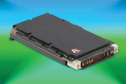
Aitech power supplies, including the company’s new rugged 3U VITA 62 P233 PSU, have added EMI/RFI L-C power filters built into the unit to help suppress RFI noise generated by the internal switching regulators within the unit.
Sometimes designing with COTS parts requires special attention to cables and connectors, Hutchinson explains. “You also can do filtering on signal lines and power cables to protect against equipment generating noise or noise in outside world,” Hutchinson adds. “You can use a filter at the interface point that will contain those emissions, and prevent them getting from one component to the other. That will only get you so far, especially when talking about trying to [apply a bandage to] an existing piece of electronics.”
Sometimes the solution involves keeping surrounding components as electronically quiet as possible. “Military standards are so high for knocking down emissions; you need to not generate the noise to begin with,” Hutchinson says. “In such situations, militarized COTS is not a viable solution; instead, it’s advantageous to use a true MIL-SPEC solution designed from the ground up to comply with EMI requirements, such as RTCA DO-160 and MIL-STD-461, and apply filtering and shielding on that, as well.”
Chassis contemplations
“Interference from external equipment or mechanical parts can cause noise and influence on analog/digital signaling of operational system,” says Dan Mor, general-purpose graphics processing unit (GPGPU) product manager at Aitech.
“Emissions from the operational system itself on external equipment, which can be mission-critical, also can disturb the proper operation of peripheral systems,” Mor says. “The system should be immune from external noise and not produce noise to the outside word. These are two main reasons why EMI/EMC is so important. Almost every new project we have — in avionics, ground fixed, ground mobile vehicles, etc. — requires EMI mitigation or EMC. Sometimes we need to prove that our products are designed and manufactured to meet these requirements and specifications.”
Incorporating EMI/RFI mitigation — and EMC — at the system chassis will help filter a majority of the energy from the power or input/output lines in question, Aitech’s Patterson says. “Tuned, low-pass filters shunt that excess energy to ground from the incoming power lines as well as susceptible signal lines, greatly reducing the potential of spurious effects.”
Each sealed ATR chassis Aitech has delivered over the past 35-plus years has an EMI/RFI filter on the power input lines to filter out incoming — and outgoing — RF radiation, Patterson says. The company’s power supplies also have added EMI/RFI L-C power filters built into the unit to help suppress RFI noise generated by the internal switching regulators within the unit. “It’s always best to suppress any potential RFI noise at the source, whenever possible,” he adds.
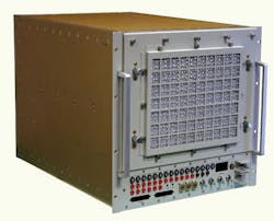
A honeycomb filter sits on the exterior of an Elma Electronics system and helps reduce EMI/RFI through the individual cells, which reflect and absorb noise.
Problematic power supplies
“As data rates become faster due to the use of Ethernet and CAN-based networks on aircraft, at the same time composites are replacing the Faraday-cage protection afforded by aluminum aerostructures, EMI/RFI mitigation is becoming increasingly important,” says Paul Hart, chief technology officer and technical fellow at Curtiss-Wright Defense Solutions in Christchurch, England.
Several EMI/RFI mitigation strategies are implemented on avionics and mission systems to guarantee reliable operation in a high electrical noise environment, Hart says. “In addition to screening of signal wires to prevent crosstalk and using separate connectors for different signal types, design of the electrical power scheme is crucial,” Hart says. “For example, conducted and radiated noise emissions from the power supply need to be minimized using filter networks. These prevent interference with other equipment in close proximity.”
Other design approaches also can come into play. “Metalwork screening and RFI gaskets around the power supply reduce stray emissions and provide further immunity from external interference,” Hart continues. “In addition, power supplies will generally isolate the input and output voltages — using isolation transformers and/or isolated DC-DC converters. These minimize stray currents by preventing multiple return paths back to ground.”
One of the main noise generators in circuits is the switching power supply, which has very fast switching transients with possibly high voltage, VPT’s Ferrell explains.
“The switching power supply chops up input voltage to give what you need on the output side,” Crystal Group’s Hutchinson says. “To get those voltages, most power supplies in the server world are switching on and off fast; every switching transient looks to the outside world like noise.”
It causes a conducted noise on the input voltage bus and a radiated noise that can couple to surrounding circuits, Ferrell says. Engineers focus on many different ways to reduce both the radiated and conducted emissions from switching power supplies.
“The testing limits are governed by a couple of different specifications. For military and aerospace applications, most customers look to MIL-STD-461 for limits on both conducted emissions and radiated emissions. VPT uses this standard along with others to ensure parts meet the noise requirements,” Ferrell says. “This is accomplished in most cases by adding an additional EMI filter that is matched to our switching power supply design. The filter in combination with proper system layout ensures the requirements are met.”
Rugged remedies
Crystal Group engineers militarize existing COTS electronics to ensure they can operate in the electromagnetic spectrum for which they were not originally designed — and power supplies present a particular challenge, Hutchinson says. “Most commercial power supplies are not inherently quiet, so we developed a team here to design power supplies from the ground up to be truly MIL-SPEC. We develop and use a custom filter targeted at the noise range you are generating.”
No matter the remedies, it seems, some nagging challenges can remain. “Given the challenges with power supplies and very tight emission restrictions, such as the more stringent RTCA DO-160 requirement for flight-based defense aviation, you just can’t [apply a bandage] and get the level of emissions required,” Hutchinson says. “We needed to have the talent here to design from ground up to not generate noise in the first place; and where you have to generate noise, like when switching frequencies, you design input filters to prevent it from getting to the outside world. When you do all that together, you end up with a total solution for the best possible performance.”

Power supplies can be one of the main noise generators in circuits, and should be examined closely to determine the best EMI and RFI mitigation techniques.
Adding an EMI filter is an excellent start to reducing conducted and radiated emissions from a switching power supply, but it also is critical that the switching power supply and EMI system layout is done properly, Ferrell says. “This includes keeping the EMI filter and power supply very close together, ensure the output of the switching power supply does not cross the input of the EMI filter, choosing an EMI filter and power supply that is enclosed in a six-sided metalization, and shielding any wires or traces going to switching loads.”
To achieve true electromagnetic compatibility (EMC), engineers and systems integrators need to look at spectrum management, Hutchinson says. “At the platform level, you need to be managing the full spectrum of your individual component suites. The best way is for every device to be compliant with MIL-STD-461. It is important to look at the total system-level impact of noise and determine if you can live with that outage or whether that frequency is something you need to go after and eliminate.”
Cabling concerns
“You can have the best-designed enclosure in the world, but if it is connected to a cable or interface that is not properly bonded or shielded, the system will radiate or be susceptible to noise throughout the environment,” Crystal Group’s Hutchinson cautions. “Other equipment can’t differentiate whether the noise is coming from your box or a cable connecting it to the vehicle — and frankly, it doesn’t matter; it’s still noise. Proper bonding and shielding of cables properly terminated at both ends are needed.”
The objective of cable shielding is essentially to keep out noise and signals external to the cable and to keep in the signal of interest, Gore’s Pino says. When a cable assembly is sensitive to EMI/RFI, the signal of interest — i.e., the signal being conveyed through the cable — can be compromised or even rendered unintelligible by interference.
“Take a full-wave antenna that’s only 9.2 centimeters at PCI Express speeds, or even less at higher PCI Express rates, for example,” Aitech’s Patterson says. “A short piece of unshielded or unprotected wire 9.2 centimeters long will resonate at 3.25 GHz, transferring all the available radiated energy of the incoming signal directly onto that I/O line. A 30 GHz high-energy radar pulse only needs an antenna approximately 1 centimeter long to create a full-wave resonant antenna.
“As the internal processor frequencies get higher, and the change-of-state margins decrease, to keep up with the demand for higher performance and throughput, dealing with EMI/EMC will continue to be a challenge,” Patterson adds. “In many cases today, systems designers will need to carefully consider the use of overbraid shielding on all the I/O cabling that runs through the platform to reduce the susceptibility to induced EMF [electromagnetic flux] from RFI and lightning strikes, both near-field and direct strikes.”
Capable cables and connectors
EMI and RFI mitigation is a growing concern for several reasons, Gore’s Pino says. “Today’s military electronic warfare (EW) and radar systems are operating at higher frequencies and higher power levels. Regarding cable assemblies in microwave applications (300 MHz to 300 GHz), as frequency increases, it becomes more challenging to effectively shield the cable assembly.
“Higher-frequency signals coupled with an increase in transmitted power can result in an increase in radiated power due to shield leakage,” Pino continues. “This combination can place electronic equipment or even other cable runs adjacent to the radiating component at greater risk for interference.” Troubleshooting a signal interference problem, especially in an aircraft, can be daunting. Effective shielding of cable assemblies and electronic components is critical to system performance, he says.
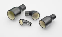
A variety of products are available, such as flanges and gasketing, to help reduce the influence of stray RF energy.
As with any technical problem, Pino says the first step toward resolution lies in understanding; and, understanding grows naturally through testing and characterization. It’s important to understand that shielding effectiveness is not strictly a cable-related phenomenon, he adds; rather, connectors and cable termination play into the equation, as well.
“For military aircraft applications, EMI/RFI challenges can be addressed through a number of tactics,” Pino says. With electronic components, use application-appropriate shielding enclosure designs,” Pino says. “In applications where cable installation or aircraft servicing can potentially damage cables, use ruggedized microwave cables with proven shield designs capable of withstanding the rigors of installation and servicing.”
Common-sense procedures can make a lot of difference, Pino says. “Ensure all coaxial connections are clean and tightened to the proper torque settings. In high-vibration environments, be sure cables are properly secured and use locking connector coupling nuts or coupling nuts drilled for lock wire holes. In microwave cable airframe installations, don’t try to stretch a cable to make a connection. Be sure to use properly sized P-clamps when securing cables. Cable placement is critical: if possible, don’t position cables in close proximity to high-power emitting antennas.”
Good advice also can go a long way, Pino says. “In commercial applications, instruct technical personnel on the finer points of proper microwave cable assembly care and handling. It is particularly important when using non-ruggedized or general-purpose cables as they are considerably more fragile than their ruggedized counterparts. Cable assembly shielding problems are often the result of damage due to improper handling. Discourage the practice of repeatedly bending cables just behind the connector or coiling cables in tight loops for storage — doing so exposes the assemblies to unnecessary wear and tear. Lastly, proper microwave connector care and maintenance is key to preserving their mechanical and electrical integrity to maintain performance.”
Cables, especially microwave cables, often are the last component to be considered when a system is under design; yet, it cannot be over-emphasized how impactful cable performance can be on overall system performance, Pino says. “Customers often treat cables as ideal or near-ideal functioning components, thinking there’s not much difference from one product to another. The common thinking is that cables simply link one critical system to another. In reality, a microwave cable is a critical system unto itself, capable of imparting unintended results in system performance. Customers rarely consider how a cable’s performance can degrade with improper handling, damage inflicted during installation, or degradation over time due to poor design or construction.”
Mitigation for military and aerospace
System complexity is only going up, which increases the need for designers to become more familiar with proper EMI reduction and shielding techniques, VPT’s Ferrell says. “EMI requirements need to be thought of at the beginning of the design to ensure compliance at the end. Failure to do so can result in long schedule delays that stem from design changes that are required due to EMI testing.”
Working with the customer in the early stages makes it much easier to consider all the factors that will affect EMI protection, Elma’s Andrew says. “We examine it from the functional board set (masking) to the backplane (crosstalk), to box (material type), to cabinet and cabling (EMC attenuation protocols). The best advice we can give is to make sure you work with the platform and component suppliers as early as possible in the development process; it’s much easier to design a system that successfully meets specs and delivers the protection required.”
Systems designers should look for every opportunity to attack EMI and RFI. “Digital frequency and component density are likely to increase, so EMI attenuation will always be a factor in system designs,” Andrew says. “There are mitigation techniques at all levels of design, from the inside out.”
EMI/RFI mitigation schemes rapidly will evolve as the energies of radiated and conducted emissions increase, Aitech’s Patterson predicts; but so far, this has been handled by a relatively simple inductor-capacitor resonant, low pass filter. “Combining inductors and capacitors has been around since the early days of heterodyne tube radios. It’s just that the Ls and Cs are getting smaller, as the frequencies and bandwidths increase.”
The RF environment, which is already filled with a variety of noise sources and interference, will only become even more crowded, Pino says. “In the future, EMI/RFI-resistant systems and components will play an even greater role in overall system reliability.”
company list
Aitech
Chatsworth, Calif.
www.rugged.com
Crystal Group
Hiawatha, Iowa
www.crystalrugged.com
Curtiss-Wright
Ashburn, Va.
www.curtisswright.com
Elma Electronic
Fremont, Calif.
www.elma.com
VPT
Blacksburg, Va.
www.vptpower.com
WL Gore
Newark, Del
www.gore.com
