Model-based design uses COTS tools for unmanned aerial systems development
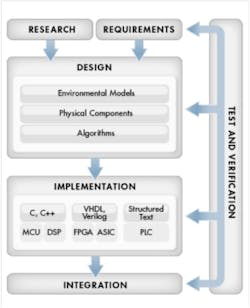
By Joy Lin, aerospace and defense industry marketing manager, MathWorks Unmanned aerial systems (UASs) are becoming more and more complex in order to fulfill a number of potentially conflicting performance and robustness requirements. However, the use traditional development methods that continue to rely on legacy designs and domain specific tools that perform subsystem-level optimization make it difficult, if not impossible to perform system-level design optimization of these complex systems. Engineers are adopting model-based design as a way to address these issues and develop and optimize designs at the system level using commercial off-the-shelf (COTS) tools. With model-based design, engineers create multi-domain models in a shared environment so that subsystems from different disciplines, such as guidance, navigation, and control (GNC) and communication, can be integrated into a common system-level model early in the process. With a system-level model, engineers can explore the design space to conduct design tradeoff studies and then refine requirements and develop requirements-based tests. Multidomain design challengesMany of today's UAS subsystem requirements are interdependent on other subsystems. However, during a traditional design process they are optimized for a specific subsystem without regard for the overall system-level impact. For example subsystem requirements for a communications system may specify a maximum bit error rate (BER), but the power needed to achieve that requirement is not given consideration in the same
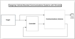
context. This then results in unnecessary rework of the design at a later stage when the power requirement is verified. To address this issue, systems engineers must perform design tradeoffs at the system level and then assess the effect that changes in one subsystem may have on performance of other subsystems and also the overall system performance. To provide meaningful results, design tradeoff studies require system-level models that capture subsystem level dependencies. For example, a typical system-level requirement for an imaging payload is to maintain a certain level of quality for the video transmission throughout flight. One design alternative to evaluate is a high gain, sophisticated control algorithm that enables the UAS to track the target within a few millimeters of accuracy coupled with a low power antenna. At the other extreme is a design with a high power antenna and a less accurate target tracking algorithm. Other design options include varying the video encoding schemes to meet the transmission quality objective. Since these alternatives are not independent, the traditional method of performing design tradeoffs using static analysis in a spreadsheet may lead to a suboptimal design -- or worse, it may lead to the conclusion that the requirements are not achievable. With model-based design, engineers build an executable multi-domain system-level model by connecting GNC and communications models with other interdependent subsystem models. Then, using a variety of subsystem level model components and running parameter sweep simulations, engineers can evaluate the output video image quality to see which design alternatives best meet the system-level performance requirement.Typically when GNC subsystem engineers develop a control algorithm, they use a mathematical model of the plant linked to a model of the control law to analyze closed-loop performance. Traditionally, plant models were developed from measured data or from first principle equations that first had to be solved in closed form so
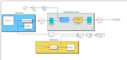
that they could be implemented in a simulation environment. Modern design tools, however, enable engineers to develop plant models, such as the antenna mechanism, composed of bodies, joints, constraints, and force elements that reflects the structure of the system itself. With this approach, the modeling environment manages all of the coordinate transformations as well as solves the underlying kinematics and dynamics of the system, enabling engineers to spend more time on using the plant model to understand system performance and develop control algorithms to meet pointing accuracy requirements. Using the closed-loop subsystem model, control engineers design and analyze the compensators and open-loop supervisory strategies. The models eliminate the need for trial-and-error design by enabling engineers to systematically tune single-loop and multi-loop control laws prior to software implementation. While GNC engineers work to ensure that the vehicle is accurately pointed at the target, communication engineers need to consider antenna geometries, communication protocols, and video encoding schemes as they work in multiple domains such as digital baseband and radio-frequency (RF). Traditionally, to meet system requirements for data transmissions, engineers developed link budgets using spreadsheets to estimate BER. With model-based design, engineers move from relying on a static link budget to being able to assess the overall video quality via simulation, which is especially important for modern compressed video transmissions. Using executable models, engineers perform system-level modeling of the communication channel, simulate baseband signal processing, and evaluate the quality of the resulting video. Then, with parameter sweep simulations, they can compute the worst-case BER to assess the robustness of the overall system -- antenna, pointing algorithm, and channel.
By combining the GNC and communications subsystem models, engineers can perform system-level tradeoff studies through simulation of design alternatives including different control algorithms, antenna geometries, communication protocols, and video encoding schemes. These studies enable engineers to optimize performance at the system level.SummaryTo meet the system-level requirements for the next generation of unmanned aerial systems, engineers can no longer rely on the traditional approach in which optimization is performed at the subsystem level and then subsystems are integrated into an overall system. Engineers need tools that enable them to perform system-level tradeoffs and observe the effects of design changes that may span multiple subsystems and multiple disciplines to avoid system integration issues and to ensure overall system performance meets requirements. model-based design with MATLAB and Simulink enables engineers from different disciplines to optimize their designs at the system level, verify high level requirements, and perform design tradeoffs before implementing the design in software or developing a hardware prototype.


