Ten tips for designing mil/aero-quality printed circuit boards

By Danit Atar, Mentor Graphics
Military and aerospace products typically need to meet IPC-A-610E Class 3 for High Performance Electronic Products standard set forth by IPC, the global trade association serving the printed board and electronics assembly industries with headquarters in Bannockburn, Illinois. This category includes products where continued high performance or performance-on-demand is critical, equipment downtime cannot be tolerated, end-use environments may be uncommonly harsh, and equipment must function when required.
Many businesses don’t have the same resources as military and aerospace companies, nor do the majority of commercial products need to meet IPC-A-610E Class 3 standards, but quality and stability are important for every product at any company. The following 10 tips, derived from proven mil/aero practices, can help improve the quality and stability of virtually any product, not just those with strict, high-end mil/aero requirements.
#1 – Make out-sourced contractors your partners
If you want contractors to provide the same quality products that you would develop in-house, make sure they feel like they’re an actual part of the team. Include them right from the start, in planning, testing, and practically everything you do. As trusted partners, you’ll get two things: Your contractors will feel more obliged to provide quality results, and you will develop a relationship in which you share a common language, making it easier to ramp up on future projects.
#2 – Every PCB that goes into military products is tested with DFM
Each of their printed circuit boards (PCBs) is tested with design for manufacturability (DFM) analysis after each and every change, even the smallest of changes. Using DFT (Design for Test), NPI (New Product Introduction) procedures, and X-ray tests are standard for all military products. It’s not just about running the tests; it’s about really analyzing the results to understand each defect and the source of the defect. Focus less on the immediate solution and more on the research and conclusions. Not only will you improve your current design, you’ll improve future designs.
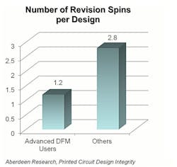
Figure 1: Running DFM tests has a significant impact on the number of revisions required to produce a working PCB.
3# – Check your manufacturer’s work and communicate your expectations
Test your first article to be sure it meets expected performance and quality definitions. Failure to test your end products can mean going back to the manufacturer to correct errors over and over again, causing missed deadlines and problems for your manufacturer. Making corrections is expensive, too. Once your manufacturer knows that product quality will be tested and that their customers are making sure they received what they ordered, they’ll start doing things differently to verify that the products they deliver work as expected. They don’t want to lose money on corrections and they don’t want to disappoint. Ensure you get what you pay for.
#4 – Designing IPC-A-610E Class 3 products is less about the design and more about manufacturing
When the goal is to create robust products that are less vulnerable to failure, manufacturing details matter. Different manufacturers may build the same product with subtle process differences. The most recent and public evidence of slightly different manufacturing techniques is the controversy around the Apple® iPhone® 6s and its power requirements. Apple sourced its A9 chip from two manufacturers. Samsung used a 14nm process and TSMC used a 16nm process. The smaller chip consumed less power, making for an embarrassing situation, albeit not catastrophic.
Printed circuit board fabricators often adjust designs to make them better fit their manufacturing processes and increase yield. For example, you may have designed a trace that is supposed to be 8 mils; however, your manufacturer might scale the artwork to, say 102 percent, because the manufacturing process results in a decrease back to the design-size on the finished PCB.
Different manufacturers enlarge artwork to different sizes and that matters. High-speed circuits and radio-frequency (RF) designs are extremely geometry-dependent. Changing trace size or spacing can result in the circuit not operating. Companies that design high-speed digital circuits, such as memory interfaces like DDR3/4, and RF circuitry inspect the final artwork before any prototype PCBs are made. Using an automated tool that identifies differences between artwork, designers can personally verify that the manufacturer’s methods will not compromise the performance of the end product.
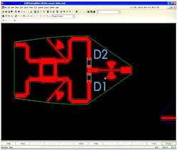
Figure 2: RF circuits use the traces as circuit elements. Any change in size or spacing geometry will most likely result in a non-operational circuit.
#5 – Know your manufacturers’ constraints
PCB fabricators can have different design constraints. If you’re aware of them during the design phase, you can avoid last-minute changes to accommodate a particular manufacturer. Build a table that includes all the known manufacturing constraints so that your designs will meet the lowest common denominator of your manufacturers. For example, if one manufacturer cannot produce boards with the same trace width as the others, you must not use traces narrower than all manufacturers can produce. This way designs can be taken to any of your manufacturers for fabrication. You will need a very organized and well maintained business information system to do that, which is not always easy, but it has great advantages.
#6 – Never compromise on quality
Make it known that your team cannot compromise on quality. Is the decision of whether to run a DFM test made by a project manager? Insist that each and every PCB be tested with DFM analysis if time and budget can tolerate it.
To make quality a culture inside an organization, it’s important for everyone to understand what they’re being asked to do. As a result, you’ll need to spend a lot of time explaining and showing your project managers the importance of the required tests as well as the costs -- in time, money, and extra work -- of not detecting these issues.
#7 – Be paranoid about quality, but know where to cut some slack
When it comes to quality, being paranoid should be a primary principle. When you make an exception to skip stages that are meant to ensure product quality, it can become a habit and can encourage skipping more and more such steps.
That being said, it’s also important to find the right balance to maintain cost-effectiveness. With DFM testing, for example, your instinct might be to switch from rarely performing the tests to doing it on all PCB designs. If this is time- or cost-prohibitive, you might slowly begin to waive DFM testing on very small PCBs, and on boards still under development. With proper experience and adequate discussion you can define places where less rigorous testing is required, but always make sure that your decision is well calculated.
#8 – Data mining to identify your failures
If you take the time and effort to analyze results from simulations and real-life failures of your products in the field, you can establish working methods and guidelines that will prevent these failures from occurring in the future. When you investigate the cause of failure, it is important to take into account as many of details as possible, starting from the materials used and how they behave under different circumstances. This is the only way to truly determine whether what you’re doing is wrong or right. Establish a learning curve within your organization, perform data mining on the information you have, and the quality and stability of your designs will increase.
#9 – Testing strategy
Devise a testing strategy for your design that fits the time and budget constraints. Some PCBs can cost upwards to $50,000 to produce, so if you’re considering physical testing such as HALT (Highly Accelerated Life Test) that will destroy your prototype, you might skip that test and choose an alternative, such as virtual HALT simulation, or choose to run very few iterations of that test.
#10 – Never stop being innovative
Always learn about new technologies, new working methods, and more testing options. If you’re aiming to produce high-quality products, you can’t just design and manufacture. You need to instill quality, innovation, and reliability at every step, especially if you’re working on high-complexity designs. Take advantage of tests such as DFT, key to meeting your goal.
Conclusion
Even as the electronic industry becomes less tolerant of product failure and low-quality products, new technologies, smaller form factors, and more complex products are driving significant increases in design complexity. To stay profitable, measures must be taken to produce stable, high-quality products on deadline.
To design high-quality, stable products, companies must make a decision to invest in that purpose. The decision needs to start at the management level but it cannot end there. Establishing a culture in your organization that encourages and proves to its employees the importance of producing high-quality products is the first step. Make sure there’s good cooperation with all the people invested in the process, take your manufacturer’s constraints under consideration during the design stage, check for failure as much as needed, and always try to learn from your mistakes.
About the author
Danit Atar is a Product Marketing Specialist at Mentor Graphics. She gained her experience in the EDA industry as a Component Database Librarian and in Customer Relations Management.
About Mentor Graphics
Mentor Graphics is the market and technology leader in PCB design, providing many of the world’s largest system design companies today with a range of scalable design solutions to reduce the time, cost and risk of electronic system design: XpeditionTM Enterprise, for the creation of today’s most complex PCB designs and the PADS® Flow, the leading Windows-based solution for PCB design. Visit the Mentor Graphics PCB division: www.mentor.com/pcb.
Images and information courtesy Mentor Graphics.
You might also like:
Subscribe today to receive all the latest aerospace technology and engineering news, delivered directly to your e-mail inbox twice a week (Tuesdays and Thursdays). Sign upfor your free subscription to the Intelligent Inbox e-newsletter at http://www.intelligent-aerospace.com/subscribe.html.
Connect with Intelligent Aerospace on social media: Twitter (@IntelligentAero), LinkedIn,Google+, and Instagram.
Relevant industry event: Embedded Real-Time Software and Systems
The ERTS² Congress (http://www.erts2016.org/about.html) is an international cross sector event on Embedded Real-Time Software and Systems for all the domains where embedded systems are central, including, but not limited to:
- aeronautics, as well as automotive, railway, subway, and marine
- satellite and space exploration
- energy
- telecommunications and wireless connectivity
- defense
- industrial control
- home automation, e-healthcare, and more
