Striving for superior SWaP in rack-mounted airborne systems
By Justin Moll, Vice President, U.S. Market Development, Pixus Technologies (www.pixustechnologies.com)
Many of today’s airborne applications have small conduction-cooled computing modules performing the basic processing and connectivity tasks in a system. Less common, but just as important, are the heavy signal processing and multifunctional computing systems that require more space. These systems are often rack-mounted in the aircraft with a front-to-rear cooling configuration. Traditionally, these systems are more bulky and heavy. We’ll take a look at ways to provide superior size, weight, and power consumption (SWaP) in these rackmount airborne systems.
The rack-mounted airborne system typically has a rugged cabinet enclosure with a powerful vacuum air system in the rear for evacuating the heat. As the cabinet enclosure often meets the heavy shock and vibration specification of MIL-STD 810G, etc, the smaller chassis computing platform sometimes does not need to meet these specs itself. But, the 19-inch chassis needs to have some ruggedization provisions.
In the P-8 Poseidon application (the aircraft that was used to search for the missing Malaysian Flight 370), a 12U AdvancedTCA chassis is the hub for the aircraft’s powerful sensors to the human-machine interface (HMI) at multiple consoles. There is significant graphics processing with multiple configurable/adjustable window screens on each console. The amount of multi-processing, video/image capture and video mixing, and communication across multiple bays is staggering. Making some broad assumptions about the system requirements, can this be achieved in another more compact architecture?
Going from 12U to 5U high… or even less
One of the key components of this type of multi-processing system with an array of video windowing and manipulation is a video mixer. This type of board typically has several inputs and outputs and performs scaling, interlacing/de-interlacing, decoding, and multi-processing. But, it is possible with newer components and efficient design to go from an 8U x 280-millimeter (mm) AdvancedTCA board to a 3U x 160mm VPX card or even a 75mm x 180mm MicroTCA (AMC) module. There are also powerful pre- and post-processors in various Intel Core i7 or Xeon or even Freescale or other types in these small form factors. They can provide 40GbE or PCIe Gen3, just like AdvancedTCA. There are AMC modules or VPX modules with global positioning system (GPS) and IRIG-B for precision timing and longstanding special protocols. Conversely, many of these functions can be performed on an FMC daugthercard on a main VPX or AMC carrier. FMCs can also provide a wealth of networking interfaces. So, from graphics to processors to switches and other specialty function modules, the smaller form factors such as OpenVPX and MicroTCA can perform the required functions for many advanced multi-computing systems.
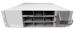
Now, a 12U or 13U AdvancedTCA chassis will hold 14 slots, typically with two switch modules and 12 payload slots. A 5U OpenVPX or MicroTCA system can provide the same slot count and today both can offer system management like AdvancedTCA. In MicroTCA, it’s a core part of the specification. In OpenVPX, the VITA 46.11 specification is going through trial use. Actually, MicroTCA can achieve these requirements in a 3U high chassis. With air intake on the front of one side of the enclosure and evacuation out the back of the system platform, a front-to-rear configuration is achieved (see Figure 1). This unit also offers dual switches (via MCHs), 12 payload slots, etc. It is also possible to use higher-power processors in this chassis example as it uses additional tongues of the connector for extra pins. Thus, where a typical AMC is limited to around 85 watts per slot, the extra pins can provide up to 120 watts per slot. This allows the use of more powerful processors in the system.
This 3U front-to-rear cooled enclosure can offer dual switch (MCH) slots and 12 payload slots like AdvancedTCA, in a much smaller size. Utilizing extra connector “tongues,” you can provide more power that typical MicroTCA systems, use more powerful processors, and/or have extra I/O pins for dedicated routing.
Note that the 3U unit recommends a max of 85 watts per slot to achieve proper cooling in this specific configuration. However, it provides up to x16 point-to-point connectivity with the use of the second tongue connector. The use of extra tongues is actually mentioned in the MicroTCA.0 specification – so using this approach does not violate the spec. The drawback of the MicroTCA.0 approach is there are not Rear Transition Modules (RTMs) available. However, it is certainly possible to utilize the MicroTCA.4 specification with double modules (approx. 150mm x 180mm) that allow RTMs to plug in. With such a design, at least six modules could be utilized in the 3U enclosure with space for several single modules (approx. 75 mm x 180mm), as well. One advantage of a 5U OpenVPX system platform (with vertically-mounted 3U OpenVPX boards) is that the RTM access would be standard.
Overall, it is theoretically possible to take a legacy 12U or 13U ATCA system and cut the overall size over 75 to 80 percent to a modern 3U chassis. It is important to note that some of these applications use more ruggedized AdvancedTCA chassis platforms (machined card guides, thicker sidewalls, and reinforced corner members, etc). In these instances, the drastic height change would not be feasible. However, there are specially designed chassis configurations that would likely add about 1U-2U to the system height. Thus a 5U specially designed chassis is feasible. Regardless, the savings in size and weight would still be significant.
The 6-slot option
The six-slot size opens up options when using the MicroTCA form factor. In that slot size, you can actually achieve six payload slots with a single MCH and redundant power options in a rugged 1U high chassis platform. The chassis is designed to meet MIL-STD-810G for shock and vibration and certainly works well in a shock-ready cabinet enclosure. In a similar approach to the 3U chassis, the 1U can also provide front-to-rear cooling, with integrated GPS/SyncE/IEEE 1588 signaling, speeds to 40G or PCIe Gen3, etc.
Extra depth for specialty devices
In many airborne applications, there is a separate device for modem, RF signaling, etc. Some designers are choosing to combine these requirements into one. In standard chassis, this is often done is small slot sizes where there is space on the side of the card cage. It is also possible to utilize specialty cards that are pluggable. Another alternative is to add extra depth to the enclosure (which is typically available in most rackmount systems). Note, the design needs to carefully address the airflow in the enclosure and ensure proper thermal management is achieved.
Space-saving cooling options
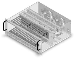
Rear-evacuative cooling solutions can pull the air directly out to the rear of the enclosure without adding enclosure height. With the fans directly in the back, less space is utilized. See Figure 2 for an example. While this can certainly do the job in many applications, systems with very high-power processors may need another approach. Further, if rear I/O is required there could be challenges in removing rear modules efficiently and having enough chassis depth available.
Powerful rear evacuative cooling solutions can keep the chassis height from increasing and dissipate enough heat for most OpenVPX systems. The higher-power systems may require reverse-impellar blowers, providing high CFM but can add 1U of chassis height.
For higher power requirements (with more challenging thermal demands), using powerful air-pulling fans above the card cage. In some traditional designs, this approach requires a lot of extra chassis height. But, there is a way to keep the chassis height to a minimum. One solution is to use fans that pull in one axis (to the top of the chassis) and blow the air out in another axis (through the rear of the chassis). Going back to the 13U AdvancedTCA system example, this solution uses these types of blowers to cool over 400 watts per slot, providing 382 CFM system airflow at 70 percent efficiency (versus 20 percent when using typical 4.7-inch tube-axial muffin fans). As this hot-swappable cooling approach only takes up 1U of the space in the chassis, it is very space efficient as well.
Optimizing SWaP
Many mil/aero applications are using low-power processors and conduction-cooled solutions. However, the higher performance systems are still using 19-inch rackmount systems. As we have seen, there are ways to reduce the size and weight of these backplane-based chassis platforms. This can be achieved with the advances in the small open-standard architectures like MicroTCA and OpenVPX. Further, there are cooling configurations and chassis orientation concepts that can further reduce the overall SWaP in your airborne application.
Search the Aerospace & Defense Buyer's Guide
You might also like:
Subscribe today to receive all the latest aerospace technology and engineering news, delivered directly to your e-mail inbox twice a week (Tuesdays and Thursdays). Sign upfor your free subscription to the Intelligent Inbox e-newsletter at http://www.intelligent-aerospace.com/subscribe.html.
Connect with Intelligent Aerospace on social media: Twitter (@IntelligentAero), LinkedIn,Google+, and Instagram.
Intelligent Aerospace
Global Aerospace Technology NetworkIntelligent Aerospace, the global aerospace technology network, reports on the latest tools, technologies, and trends of vital importance to aerospace professionals involved in air traffic control, airport operations, satellites and space, and commercial and military avionics on fixed-wing, rotor-wing, and unmanned aircraft throughout the world.


