In safe hands: requirement-based testing for design assurance of complex, safety-critical components with high impacts of failure

By Louie de Luna, DO-254 Program Manager, Aldec
Developed in the 1990s by the RTCA SC-180 committee, DO-254, Design Assurance Guidance for Airborne Electronic Hardware was published in the year 2000. In 2005, the Federal Aviation Administration (FAA) Advisory Circular (AC 20-152) recognized DO-254 as a means of compliance to the federal aviation regulations when complex custom micro-coded components are used in airborne systems.
The document’s style is very much objectives-based, in that it spends a great deal of time explaining what should be done. For example, any errors introduced into the design must be caught to ensure the end product will function as intended, rather than explaining how to meet the objectives. This style, and the fact that there are few, if any, examples within the document, have given DO-254 a great lease of life; important when one considers that work on the standard commenced well over 17 years ago. Look at what has happened in the electronics industry during that timeframe.
Today, the FAA recognizes the role electronic design automation (EDA) tools, used throughout the development life cycle of complex custom micro-coded components – such as ASICs, PLDs, and FPGAs – can play in demonstrating DO-254 compliance. In this respect, the EDA tools would be used for simulation, synthesis, place and route, and static timing analysis, for example. However, the FAA also recognizes that other forms of EDA tools – most notably those that push harder into the verification space and/or provide traceability – can provide further design assurance for components with high impacts of failure. Specifically, the FAA has defined five hardware Design Assurance Levels (DALs). Designers working on systems categorized as DAL A (catastrophic consequence of failure) and DAL B (hazardous/severe consequence) must be able to produce a great deal of documented and traceable verification data, compared to designers working on systems with less or no consequence of failure.
In-hardware
As defined in RTCA/DO-254 section 6.2.1, DO-254 requires that safety- and mission-critical designs be verified on real hardware. But therein lies a problem. For example, FPGAs are being used more and more in the aerospace industry. Indeed, a large FPGA, possibly with a microprocessor core, might contain most of the board’s primary (and certainly its time-critical) functions. It will also typically connect with a host of other board-mounted components, such as micros, DSPs, memory devices, and possibly other FPGAs.
Requirements-based physical testing using the target circuit board is required for DAL A and B FPGAs, but this is not feasible in most cases. It is seldom possible to drive the target FPGA and capture the outputs as defined in the requirements and test cases, because not all pins/pads will be accessible.
Aldec’s solution to this problem was to develop a bit-accurate, in-hardware verification environment that enables requirements-based testing at the target FPGA, at speed, using requirements-based test vectors from the RTL simulation environment. In 2007, Aldec launched its DO-254 Compliance Test System or CTS (Figure 1), the company’s first product positioned for DO-254 projects.
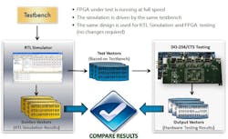
Figure 1: Aldec’s DO-254/CTS facilitates at-speed, in-hardware verification of FPGAs.
The CTS comprises:
- A custom daughterboard that contains a target FPGA (i.e., the one to be verified);
- A commercial off-the-shelf (COTS) PCIe motherboard for sending test vectors to and capturing results from the daughterboard; and
- Compliance software for test vector generation, at speed testing and results comparison.
The CTS has a plug-in for storing the sequences of stimulators and events (outputs) produced during the RTL simulations. This generates two sets of test vectors for all test benches: Golden Vectors, which are the RTL simulation results and which will be used for comparison purposes; and Input Vectors, which will be used for the at-speed, in-hardware verification. The Input Vectors are uploaded from a workstation to the motherboard. The CTS application software then controls the in-hardware verification process by feeding the Input Vectors to the FPGA pins at speed using real clocks. Moreover, the process is completed automatically without adding any wrappers to the vector set; which would otherwise adversely affect requirements traceability under DO-254.
The results obtained during in-hardware verification are then sampled at-speed and recorded in a waveform file. Compliance software then automatically compares the in-hardware verification results (i.e., Output Vectors) with the Golden Vectors (i.e., RTL simulation results).
Linting
As DO-254 is effectively a “best practice” document it should come as no surprise that adherence to coding standards is seen as a crucial aspect of design assurance for FPGA-based safety-critical applications and the use of HDL coding standards is recommended by the FAA in Order 8110.105-2.a. However, for any given project, the HDL coding standards must be defined, reviewed, and documented, which is an extremely lengthy process.
To address this, in 2009, Aldec developed a DO-254 plug-in for its ALINT linting tool, which a fully automated design rule checker (Figure 2). The DO-254 plug-in for ALINT, and ALINT-PRO (launched in 2015) includes checks for style, readability, simulation, clock/reset management, design re-use, coding for safe synthesis and implementation, clock domain crossings, and design for test – in both VHDL and Verilog HDLs.
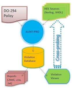
Figure 2: The DO-254 best practice coding stands feed into ALINT-PRO.
In terms of target hardware, the aerospace sector is increasingly relying on FPGAs for far more than just glue logic. Large gate-count FPGAs, able to accommodate designs with multiple clock domains, are proving popular. However, with logic frequently making clock domain crossings (CDCs) the misalignment of clocks can potentially lead to metastability and data coherence problems. In this respect, ALINT-PRO includes CDC checking, comprising static verification, design constraints setup, and dynamic functional verification.
As rule checkers, both ALINT and ALINT-PRO will flag violations. Correcting the design and/or coding style will clear the violations in a subsequent run. Or the user can mark violations as “irrelevant,” provided justifications (i.e., comments) are made.
Both ALINT and ALINT-PRO can output information essential for audits and reporting and review purposes.
Traceability
Developing FPGAs for DO-254 compliance requires submitting extensive documentation to a Designated Engineering Representative (DER); documentation that provides complete traceability throughout the development life cycle of the equipment (for example, a line replaceable unit, LRU) including any complex custom micro-coded components used therein.
To help designers provide full traceability, Aldec launched Spec-TRACER in 2013. It streamlines the requirements engineering process from capture through to tests management. FPGA requirements are automatically traced down to HDL design and test bench sources, thus allowing designers to record how every requirement (within the spec) was implemented and verified. Moreover, gaps (i.e., parts of the spec’ not implemented and verified), as well as unused HDL functions, are easily exposed – so the result is not just about “completeness” but identifying wastage too.
Spec-TRACER also offers several traceability flows that can be easily adopted. A common traceability flow is shown in Figure 3, where the FPGA requirements reside in IBM Rational DOORS, HDL source code in Notepad++, and Test Cases in Word Doc.
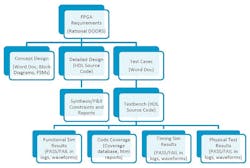
Figure 3: Spec-TRACER is able to connect and maintain traceability from various sources.
In addition, and as we are all aware, requirements can and do change throughout a typical project. However, if requirement changes are not properly managed they will almost certainly result in program delays. This is because even a single change to the requirements (spec) can impact so many aspects of the design and its verification. Impacts of requirements change can include subsequent changes to: lines of code in the HDL design; requirements-based test cases; lines of code in the test bench files (and other aspects of the verification environment); simulation runs; code coverage analysis (reports, waveforms and log files); synthesis; timing; and placement constraints.
To this end, Spec-TRACER is equipped with built-in reporting for Impact Analysis, and it can determine the magnitude of any and all changes before changes are made. As you can imagine, with the growing size and complexity of modern FPGA/ASIC-based designs – which might have hundreds of requirements within the spec and thousands of implemented elements to meet those requirements, running Impact Analysis helps engineers appreciate the extent of the knock-on effects and the ramifications for the overall program.
Tool qualification
Aldec has done the due diligence to rigorously test its tools according to the stringent process defined in RTCA/DO-254 Section 11.4 Tool Assessment and Qualification Process. Whenever feasible, Aldec recommends manual review of the verification results in order to claim independent assessment. If manual review is not feasible, then Aldec provides specific Tool Qualification Data Packages for specific Aldec DO-254 tools.
In 2015, Aldec released tool qualification data package for CTS. Avionics certification authorities consider CTS a verification tool and, therefore, it must go through stringent tool assessment and qualification. Tool qualification can be a huge undertaking if done by the avionics supplier, especially if done with limited or no help from the tool vendor. As a tool vendor, Aldec believes in providing high-quality support to customers, thereby testing CTS by means of a structured tool qualification process (defined in RTCA/DO-254) such that it will not fail to detect any design errors.
The data package includes Tool Qualification Plan, Tool Operational Requirements, Tool Test Plan and Test Results, and Tool Qualification Accomplishment Summary, all of which can be easily adapted by the applicant into their life-cycle data.
Training and templates
DO-254 (as a document) is very objectives-based and explains what must be done to achieve compliance but not necessarily how it should be done. Aldec has, since 2011, been running annual DO-254 training seminars. Content includes but is not limited to a background to DO-254; writing, organizing, and optimizing requirements for verification; how to make verification less difficult (and by extension less time-consuming and less expensive); and how to perform elemental analysis for DAL A and B hardware.
Also helping engineers cope with DO-254 compliance is the addition of document templates and review checklists to Spec-TRACER (2016.12 release). These additions were developed by an FAA consultant DER through many years of auditing DO-254 programs – ones with DAL A, B, C, and D FPGAs. The templates and checklists help organizations new to DO-254 and are also of benefit to manage compliance though a single tool because engineers and other stakeholders can capture, manage versions and revisions, conduct reviews, and generate reports.
IDE
Able to play a significant role in the development and verification of an FPGA for an application requiring DO-254 compliance is Aldec’s flagship product, Active-HDL. It is an Integrated Design Environment (IDE) that provides mixed-language (VHDL, Verilog/SystemVerilog, C/C++, SystemC, OVA, and PSL) high-performance simulation and advanced debugging for Windows and Linux operating systems. Within Block Diagram Editor and Finite State Machine Editor are tools for the graphical entry of VHDL, Verilog, and EDIF designs. The tool’s Code2Graphics converter can automatically translate VHDL, Verilog/SystemVerilog, and EDIF netlists into block diagrams and state diagrams.
During DO-254 concept design process, the combined use of Block Diagram Editor, Finite State Machine Editor, and Code2Graphics helps conceptualize the architecture, functional diagram, major functions, and dataflow of the FPGA design.
The tool’s HDL Editor is tightly integrated with Active-HDL’s compiler and simulator to enable debugging capabilities. Features include keyword highlighting support for code groups and code structure, auto-complete and auto-format, bookmarks and named bookmarks for easy navigation through source code, breakpoints, and columns selection.
Aiding verification and validation, code coverage is generated automatically (from source code) within Active-HDL; noting here that for DAL A and B designs, the FAA recommends the use of code coverage to satisfy Elemental Analysis, an advanced verification method described in RTCA/DO-254 Appendix B 3.3.1.
The following types of code coverage are available from Active-HDL:
· Statement coverage – examines each executable statement and counts the number of times it has been executed.
· Branch coverage – examines branches of each conditional statement and counts true or false conditions that have been met by a branch during simulation.
· Path coverage – examines the order of conditional statements execution and indicates whether all possible execution sequences have been verified by a test bench.
· Expression coverage – monitors logical expressions and indicates whether all possible states of a logical expression were exercised.
· Finite State Machine coverage - determines which states and transitions in the state machine diagram have been executed during simulation.
· Toggle coverage – monitors signals logic value changes and indicates signals that were not exercised properly by a test bench.
A decade on from Aldec’s first engagement with a customer needing to comply to DO-254, the company has brought to market both software and hardware solutions, as well as training, to help design engineers (Figure 4).
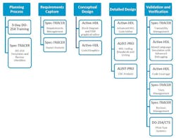
Aldec’s DO-254/CTS has been employed on 60+ completed DO-254 projects with several major avionics suppliers developing systems for flight control, engine control, actuation, landing gear, and graphical display systems.
Search the Aerospace & Defense Buyer's Guide
The go-to resource for Intelligent Aerospace technology news & information:
Covering key topics
Across all market segments
Subscribe to the free Intelligent Inbox e-newsletter
Subscribe to receive all the latest aerospace technology news & information, delivered directly to your e-mail inbox twice a week (Tuesdays and Thursdays). Sign upfor your free subscription to the Intelligent Inbox e-newsletter at http://www.intelligent-aerospace.com/subscribe.html.
Connect on social media
Keep pace with aerospace innovation and opportunities via your favorite social media channels. Connect with Intelligent Aerospace on Twitter (@IntelligentAero), LinkedIn,Google+, and Instagram.