Heat pipes & vapor chambers: conduction cooling stalwart
By George Meyer, CEO of Celsia Inc.
For more than 50 years, the military/aerospace (mil/aero) market has relied on heat pipes and vapor chambers to enhance conduction-cooled electronic devices. More exotic alternatives are now available, but these simple devices will remain a mainstay in the thermal engineering toolbox for the foreseeable future. They’re dependable, relatively inexpensive, long lasting, and versatile. Most people know what heat pipes look like, but only the initiated few understand how they work and how engineers use them to cool mission-critical components – until now.
Inner workings of heat pipes and vapor chambers
Heat pipes and one-piece vapor chambers begin life as a copper (usually) tube with a porous sintered metal applied to the inside walls. Two-piece vapor chambers start as two stamped copper plates with each inner wall containing sintered metal. The sintered material acts like a sponge, absorbing a small amount of added liquid and distributing it to drier areas. Try sticking one edge of a sponge in water. Even when held vertically, the top will eventually get wet. The capillary action used in heat pipes is identical to the sponge – it acts as a passive pump moving liquid from wet areas to dry ones.
Next, air is removed from the vessel and sealed creating a vacuum that allows the liquid to turn to vapor at temperatures well below 100 degrees Celsius.
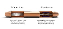
As the semiconductor warms, the attached heat pipes or vapor chambers absorb heat through the copper walls of the pipe and into the liquid soaked sintered wick. The liquid turns to vapor which travels toward the fin stack (condenser). There it cools and returns to liquid which is absorbed by the wick and “pumped” back to the heat source. The cycle repeats.
They work so well because of very high thermal conductivities
Many articles dealing with terrestrial thermal challenges neatly place cooling solutions into one of three categories: convection, conduction, and liquid. While this is a good high-level explanation, it fails to highlight a very simple truth: At some point in the thermal cycle, convection and conduction will almost certainly play a role in cooling a semiconductor. The former happens because heat eventually needs to be dissipated into the air. The latter because total powers and power densities – the number of watts that need to be cooled per square millimeter of die area – have been rapidly increasing, requiring heat to be spread over a larger area than provided by the die face.
Even with an absurdly large amount of forced air across a naked higher-power semiconductor, it’s going to burn up, shut down, or throttle back IC capability to a trickle. Simply put, the area connected to and above the IC needs to be increased to move or spread heat to a place where it can be dissipated into the environment. Here’s where heat pipes and vapor chambers can come in handy.

Both a simple finned heat sink that sits directly atop an IC and a pumped liquid solution need a solid aluminum or copper base that attaches to the die. These materials have thermal conductivities of around 200 and 400 watts per meter Kelvin (W/m-K) – basically a measure of their ability to transfer heat away from the die surface. For liquid cooled systems, it’s usually high enough. But remove pumped liquid from the equation and two-phase devices quickly come into the mix.
Heat pipes as short as 75 millimeters (mm) have a thermal conductivity of 6,000 to 10,000 W/m-K, much higher for longer lengths. That’s minimally 10 to 20 times the heat transport capability of copper. This becomes important when heat needs to me moved or spread beyond the capability of solid metal alternatives. Engineers know when the thermal resistance in the base is larger than roughly 10 degrees Celsius, heat pipes or vapor chambers should be considered. You can try it out using our vapor chamber delta-T calculator or heat pipe performance calculator.
Difference between heat pipes and vapor chambers
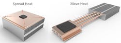
Once engineers determine that traditional solid heat sinks won’t work or have ruled out liquid cooling – for a variety of reasons – they usually turn to two-phase options. While there’s no hard rule for choosing between heat pipes and vapor chambers, the general guideline is to use heat pipes to move heat to a remote heat sink and use vapor chambers to spread it to a local heat sink.
The above graphic shows a heat sink (fin stack) that’s internal to the device, but it doesn’t have to be. Sealed or semi-sealed enclosures usually have no internal fan. That means that heat from the hottest running components need to be directly connected to the enclosure wall(s) which are usually finned on the exterior.
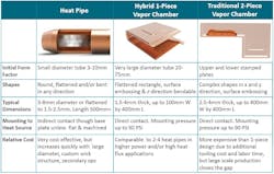
Often, moving the heat to a case requires the two-phase device to be in a U-shape – one side touching the component and the other making contact with the enclosure wall. Although it’s easy to bend heat pipes into this configuration, it’s been a stumbling block for vapor chambers. Fortunately, more manufacturers are beginning to produce one-piece designs. Rather than use two stamped plates as in a traditional vapor chamber, they use very large 20mm to 75mm tubes that are flattened and easily bent into a variety of shapes along the Z-axis.
Whichever two-device device is chosen, performance can be finely tuned to meet application requirements. These include changes to wall thickness, wick type, wick structure, and fluid loading. Additionally, different enclosure and liquid combinations can be used to fit most usage conditions. With 20+ year durability, passive operation, and enclosure/liquid combinations to fit most environments, heat pipes and vapor chambers have proven themselves indispensable thermal components.
About the author
George Meyer is a thermal industry veteran with over three decades of experience in electronics thermal management. He currently serves as the CEO of Celsia Inc., a design and manufacturing company specializing in custom heat sink assemblies using heat pipes and vapor chambers. Previously, Meyer spent 28 years with Thermacore in various executive roles including Chairman of the company’s Taiwan operations. He holds over 70 patents in heat sink and heat pipe technologies and serves as a chairperson for both Semi-Therm and IMAPS thermal conferences in the San Francisco area.
