Wireless ‘ghost’ connections make data and power transmissions without physical contact a reality
Over 100 years ago, when Nikola Tesla illuminated light bulbs that he held in his hands, it looked like a magic trick. Today, the principle of induction used by the Tesla Coil to make electrons flow wirelessly across space — the same principle used by electric toothbrush chargers and wireless charging pads for smartphones — is being employed for more demanding applications. In fact, recent developments in wireless connectivity are giving military product designers new options for transmitting power or signals through air or water without the need for a direct physical connection. Neither magic nor science fiction, wireless connection technology is now a real possibility in a wide range of applications where a wired connection was previously difficult or impossible to implement.
Situations where a wireless connection may be an option
A wireless connection solution can be defined as a hybrid interconnection system using either non-contact power or non-contact data technology to make a connection over a short distance without using physical media. For product designers, opportunities to implement a wireless connection may appear whenever:
- Body armor, helmets, uniforms or other clothing make using wires or wiring harnesses unmanageable or dangerous.
- Container walls or surfaces that separate two fluids or two different pressurized environments, such as submarine/submerged vessels, pressurized tanks, or nuclear applications, make it impractical to use a penetration where a catastrophic leak could occur.
- Penetrations in structures need substantial local reinforcement to maintain the load path.
- Moving parts -- such as helicopter blades, wind turbines, fans, and even industrial robot applications — create an environment where stresses, vibration, or friction could destroy wiring and contacts.
- Tight areas where thermal or acoustic insulation is breached to allow wiring and conduit to pass through make it difficult to apply sealants or gaskets around the penetration.
- Multiple connections/disconnections make it difficult for physical limitations in materials or plating to provide the necessary friction to ensure positive contact.
- Accessibility difficulties do not allow sufficient space or visibility to enable safe, repeatable connections.
- Automatic disconnection must occur at the precise moment of drop or launch in launchers, missiles, or weapons.
- Alternatives to wiring and conduit make life more convenient in everyday workspaces, furnishings, or mobile gear by eliminating the hassles of physical power or data connections.
Further indication that a wireless connection may be an option is when a “yes” answer is given to these questions: Is the environment harsh and safety-critical? Is transmission through water? Must arcing be minimized or eliminated? Is a penetration required through metal? Will background noise interfere with transmission?
How does wireless connectivity work?
While knowledge about the principle of induction is over a century old, understanding how to apply it in various situations has deepened in recent decades. Before smartphone charging stations, an important application was aircraft tire monitoring systems developed in the late 1970s to measure and transmit pressure data without any physical contact. Since then, opportunities to transfer power and data across small distances through inductive coupling have increased as the technology has evolved.
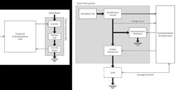
The design of a wireless connectivity system employs two basic components: A transmitter (primary coil) and a receiver (secondary coil), as shown in Figure 1. In a wireless power system, for example, the transmitter circuitry generates a high frequency alternating magnetic field around the transmitter coil. This coil is coupled to the receptor coil and, through inductance, the magnetic field is converted to electrical energy, which can then be used to power other circuitry.
Figure 1: Block diagram showing primary coil of transmitter (left) and secondary coil of receiver (right).
To illustrate how the two components function, consider a robotics application: The transmitter in a stationary robot arm transfers power inductively to a receiver on a rotating, indexing or fixed mobile part, like a gripper. The mobile part can then make power available to power sensors, heaters, cameras, valves, microprocessors or batteries. Although the transmitter and receiver are separate, they function as an inductively coupled device that can operate in very demanding environments—underwater, clean rooms, or in the presence of grease or mud contaminants — with little or no maintenance.
Overcoming design challenges
The primary goal in any wireless connection design is reliable transmission of power or data across a space in an environment where a wired connection is not desired. Several factors challenge the effectiveness of transmission across the gap, namely:
1) Efficiency:
Inefficiency in the system creates thermal stress. Energy that is not transmitted efficiently is converted into heat. In low power devices, however, efficiency is not a problem because the amount of heat can be easily managed. For example, if the application requires 10 watts and efficiency is around 70%, then the 30% loss translates into three watts, which does not usually pose environmental or safety problems. But in a 100-watt application, 30 watts of heat -- which is equivalent to a small light bulb or small soldering iron -- can create difficulties; 1,000-watt applications with 300 watt losses may cause substantial thermal problems.
Consequently, efficiency is a key parameter in wireless connection designs. Recent advances in coils and proprietary electronics developed by TE Connectivity (TE) have demonstrated efficiencies of approximately 90 percent to 94 percent, an efficiency level that can help minimize thermal concerns.
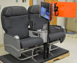
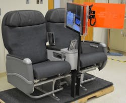
Figure 2: Business-class airline seat with conventional connections for a video display (right) and a display that employs a wireless connection system (left). (Credit: TE Connectivity)
2) EMI-EMC:
Electromagnetic interference (EMI) and electromagnetic compatibility (EMC) are serious issues in aerospace and defense applications. By its nature, when a conductor is powered up, “parasitic” energy is generated. The coil acts as an antenna that emits energy that impacts surrounding equipment. To minimize electromagnetic problems, printed circuit board (PCB) designs and electronics have been developed to enable wireless contact systems to meet avionics standard DO-160 Environmental Conditions and Test Procedures for Airborne Equipment.
3) Adaptability:
Transmission distance is a critical factor in the performance of wireless connected system. Developments now enable an inductively coupled system to optimize efficiency despite variations in the gap between the transmitter and the receiver. This capability enables applications where motion, displacement or vibrations would otherwise interrupt transmissions over conventional wireless transmitter-receiver technologies.
4) Data transmission:
Different options are available for wireless data connections depending on the environment:
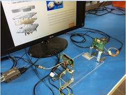
- In air, the transmitter is used as a proximity antenna for a 60 GHz RF link (Figure 3). TE engineering would recommend this solution when the gap is not larger than 20 cm and the allowance for misalignment is not greater than 5 cm. Separation and offset depend on the directionality and gain of the antenna. The described configuration can support a data rate above 400 Mb/s.
- Underwater, a wireless connection solution can be devised with a 60 GHz bandwidth that can withstand signal absorption by seawater above 104 dB/m.
- Optic solutions have been explored for data rates above 1 Gb/s. Based on the principle of collimated beam technology, a laboratory demonstration by TE has successfully transmitted 12 Gb/s through a 5 mm gap using transparent materials within a (-45°C - to +145°C) temperature range. A free space optics solution is also feasible, provided there is an allowance for a suitable offset and a standard chip is used in conjunction with a wide-area detector or a detector array for faster application.
By meeting these challenges, advanced wireless connection technologies are providing new options for robust, nonphysical connectivity in more ways than military product designers may have thought possible just a few years ago. Wireless connectively platforms are capable of facilitating a wide range of product innovations. Design assistance and evaluation kits are available to help product designers realize those possibilities today.
Figure 3: 60Ghz RF link wireless data connection between a monitor and a Video Graphic Array (VGA) signal source. (Credit: TE Connectivity)
