Flexible shafts for aerospace manual valve control override systems
By Stephen Grimes, Director of Sales and Marketing, S.S. White
Manual override systems are critical to airlines’ increased expectation for on time departures. Backup manual valve control override systems are typically used after a failure of a system or mechanism that is normally operated by other indirect means, such as an electro mechanical system. Such backup systems often feature a flexible shaft, which can transmit rotary motion, but can be routed over, under, and around obstacles to reach a valve that can be located deep within an engine. Flexible shaft design must consider torsional deflection, breakout torque, routing to minimize bends, vibration, and ergonomic/user interface issues, as well as temperature and altitude factors.
The importance of backup manual override systems
Manual override systems are often used for valves controlling the flow of a physical medium, such as a liquid or a gas. In the event of a failure, the ground crew, mechanic, or pilot can use the manual override to actuate the system.
Manual override systems are critical to airlines – and are becoming more so – due to increasing expectations for improved reliability and on time dispatches. Backup manual override systems allow the aircraft to be dispatched from the gate and continue its planned flight. They avoid delays, including de-bagging and off-loading passengers while finding another aircraft. Ultimately, they play an important role in avoiding expense for the airlines and delays for paying passengers.
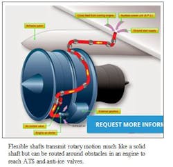
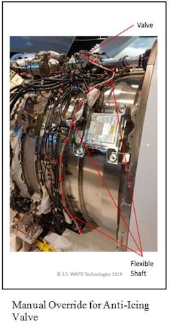
Backup manual overrides often use a flexible shaft that brings actuation to a convenient position where the user (pilot/mechanic) can remotely operate the valve after popping open a hatch to access the shaft. In these complex systems, equipment is often located in a highly inaccessible location. The flexible shaft brings the override position to somewhere much more accessible. It allows the valve to be actuated manually from a remote location, or it enables the override to be located at a convenient location.
It should be noted that flexible shaft backup systems are a one-time fix; when the aircraft reaches its destination, the faulty valve is usually swapped out for a new one to reduce “down time”. The concept being that the airline contacts its destination and schedules maintenance and/or finds a replacement airplane.
Flexible shaft basics
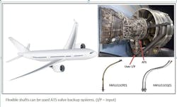
Flexible shafts are frequently used in backup systems for air turbine starter (ATS) valves – part of the system that starts the aircraft’s main engines. When the aircraft is on the ground, the power supply generates compressed air to spin the main engines to start, providing power for aircraft cabin air and instruments. Another common use is on anti-ice valves, which enable hot air from the engines to be used to prevent ice buildup on engine intakes and wing leading edges.
For example, S.S. White has designed and developed several flexible shaft assemblies to manually actuate (control/override) valves in the event the automated system fails. Applications for ATS valves include the CFM International LEAP1 high-bypass turbofan, and the GE9X high-bypass turbofan for the Boeing 777X.
Key design factors for flexible shafts
The key design factors to be considered in developing a flexible shaft for aerospace manual override applications are torsional deflection, breakout torque, routing to minimize bends, vibration, and ergonomic/user interface.
Flexible shafts for manual override applications must be designed with just the right amount of torsional deflection to enable the user/operator to “feel” if the valve has moved – and how much. Torsional deflection is a function of the shaft’s characteristics and is generally proportional to length. If the flexible shaft is to be turned a prescribed number of full revolutions, the “feel” is important to know the position of the valve. The torsional deflection is designed to meet the specification for the amount of angular deflection – the allowed angle of lost motion.
Another key design criterion is breakout torque, the additional torque (rotational force) needed to overcome any initial stiction, defined as the static friction that needs to be overcome to enable relative motion of stationary objects in contact. If a valve has failed to operate in its automatic configuration for some reason, there may be a mechanical obstruction causing the non-operation. If that is the case, the initial torque applied to the flexible shaft might be higher to initiate movement than once movement has been initiated.
The routing of the flexible shaft should be as sympathetic as possible, avoiding tight bends and minimizing the number of bends. This reduces stress and maximizes shaft life. In addition, bends induce internal friction, which can lead to an increased loss of “feel” due to additional torsional deflection. There is resistance to overcome within the system itself – if the flexible shaft is 6 feet long and has 8 bends, it will contact each position and must overcome friction at each one. Avoiding tight bends and minimizing bends altogether improves the feel for the user/operator. With less twist angle, there will be less lost motion and improved feel.
Vibration is also a factor in manual override applications. The shaft will be subjected to vibrations while it is stationary for long periods in the same location and orientation in an aircraft engine. Because it does not move unless there is a (rare) failure event, it sits in one position and is vulnerable to failure from vibration. Also, if it is not being used, there will be no sign that its characteristics have changed. Flexible shaft designers therefore have to reduce exposure to extremes of vibration and conduct more analysis to determine the potential for such failure. They may have to support or restrain the shaft in more or different ways to minimize this effect.
User interface and ergonomics
Human factors and ergonomics affect the ability of the operator to use the device and must be considered in the design. Factors to be considered include the location of the device, the force needed to operate it, temperature of surrounding surfaces, and need for glove use, among other design considerations.
The user interface, where the user places their hand or tool to operate the flexible shaft, can take a variety of forms. Examples include a male or female receiver for a standard wrench, or a crank handle that is an integral part of the flexible shaft assembly. In cold locations where operators would be wearing bulky gloves, sufficient space around the device would be required, especially if operators have to disengage a lock before they rotate the shaft. Similarly, if there is a hot surface next to the device, the shaft would have to be located far enough from the operator to avoid a burning injury.
Temperature and altitude considerations for flexible shaft designs
There are two competing points of view on how to accomplish this. One is to lubricate the flexible shaft assembly, in which case the system must be sealed to retain the lubricant. If a system has to be lubricated because of temperature or altitude, the seal must be good enough that air does not cycle in and out allowing condensate to build up and freeze.
The other school of thought is that the system should not be lubricated but kept dry. This option is feasible due to the low number of operating cycles associated with an override application. A non-lubricated system eliminates the need for seals but lets the changing external environment into the system. Water may ingress and condensation may occur, so a drain hole would be needed at the lowest point.
Flexible shafts play an important role
In an aircraft, the electrical system operates automatically, but when there is a failure, flexible shafts can play an important part in manual override systems that can keep planes flying. Using flexible shafts in an aircraft design helps to improve aircraft serviceability ratings; the reliability analysis of these parts contributes to that of the whole aircraft.


