Competition for new display applications
By J.R. Wilson
The evolution of rear-projection display technology not only is influencing the choice of every system component, but also has begun to challenge the very definitions of "rear" and "projection" as engineers push the envelopes of brightness, resolution, size, weight, cost, application, and flexibility.
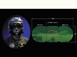
These expanding applications include replacing cockpit cathode ray tubes (CRTs) and traditional head-up displays (HUDs) with rear projection-based systems. This enables systems integrators in the field to link several small displays together quickly into a single large display for group briefings and even for three-dimensional displays viewable in normal lighting that require no special glasses."In any application where there is already a big CRT, a projection design is an option because the space is there for the projection," says Darrel Hopper, principal electronics engineer for displays at the U.S. Air Force Research Laboratory at Wright-Patterson Air Force Base in Dayton, Ohio.
Hopper notes the center 8-by-8-inch display in the new F-22 jet fighter cockpit is a rear-screen projector. This device uses a light engine based on a reflective liquid crystal display (LCD). This display is similar to an active matrix LCD (AMLCD), but in reflective rather than transmissive mode — somewhat akin to the technology in a camcorder viewfinder.
This new generation of rear projection technology also is going into one of the oldest aircraft in the active Air Force bomber Fleet—the B-52— which Pentagon leaders havevowed to keep flying for nearly another half century. Toward that end, Air Force officers are expected to spend several billion dollars on upgrades in the next decade, including end-to-end replacement of electronics and displays.
One of those is a 9-inch CRT found in several crew positions on the B-52 and the newer B-1 bomber. With no available source of resupply for this unit, Air Force experts are opting to pull the CRT. One replacement system under development is the Polyplanar Optic Display (POD) using a Texas Instruments Digital Micro-mirror Device (DMD, now the property of Raytheon), which engineers can size to fit into the space of the old CRT box.
Driving that development is the need for a high-resolution forward-looking infrared image, along with a low-light TV image, at the B-52 pilot/co-pilot position.
Elsewhere in the cockpit, engineers at Flight Visions Inc. of Sugar Grove, Ill., are developing a small, light, inexpensive HUD to eliminate a CRT. Flight Visions president Bob Atac says his engineers already have resolved most issues, leaving them to concentrate on replacing the CRT. Engineers are looking at AMLCD, digital light processing (DLP), grating light valve (GLV), benefit from and lasers. AMLCD and DLP are furthest along in development.
Flight Visions will file an interim report with the Air Force by November, with a final report due in February 2000. A job to produce a prototype will be opened for bids in November. Overall, intense competition is building for new rear projection display systems for military applications — especially in the cockpit — that will use existing commercial and military research.
Engineers can cover many of the environmental factors unique to military applications — shock, vibration, and G-forces — with packaging rather than altering components. That has been the solution for the horizontal large-screen display going into the U.S. Navy`s new Virginia-class attack submarine as an electronic map table.
One of the biggest challenges is meeting the new requirement for out-the-window 20-by-20 vision in flight simulators. This would enable pilots to see at the same resolution in a simulator as they can in real life. This is mandatory if simulators are to be used for mission rehearsal — an increasingly important application. The limiting factor in achieving this goal has been projector resolution. Current rear projection systems use eight projectors, each capable of producing about 2 million pixels, which is only 10 percent of the number required to achieve a resolution equivalent to 20-by-20 vision.
Several initiatives seek to improve these projectors. One is to replace existing arc lamps with solid-state lasers to brighten and sharpen images. Another is a $3 million, 3-year effort by Evans & Sutherland in Salt Lake City for the Air Force to develop projectors capable of displaying 25 million pixels each.
Interest is growing in 3-D projectors, which are based on voxels (volume elements) instead of two-dimensional pixels (picture elements). A true 3-D display causes a different perspective to enter the user`s left and right eye, with these perspectives changing constantly as the user moves his head.
The Navy is one of the most enthusiastic advocates of 3D displays, especially for such applications as the Aegis shipboard combat system aboard Ticonderoga-class cruisers (CG-47), and Arleigh Burke-class destroyers (DDG-51). The theory is to present a true 3D representation of airspace in a combat zone.
But airspace is not the only scenario in which 3D could apply. Navy leaders also would like to see such displays of the seaspace surrounding submarines, for example, and perhaps a combined air above/water below view for surface ships. Army officials, meanwhile, are interested in a good picture of the land and airspace around battlefields.
With improving technologies at all component levels, rear projection is getting a new hold on a wide range of applications. These include workstation and cockpit displays, HUDs, training and mission rehearsal simulators, and command and control systems. And the technologies involved in reaching new levels of resolution, brightness, and even perspective are growing increasingly diverse as new materials and theories come into play.
The cutting edge
Those breaking new ground are enthusiastic about where their efforts are leading, and are extremely sensitive to potential competition in getting there. As a result, they tend to be circumspect when it comes to details.
One such developer is Elizabeth Downing, president of 3D Technology Laboratories (3DTL) in Sunnyvale, Calif., who has made few public pronouncements since shortly after founding her company in 1996. 3DTL is in place to pursue a new approach to 3D called a volumetric crossbeam display.
Unlike other approaches, Downing`s does not create an image that appears to be three-dimensional, but rather draws an image within a solid block of material that is actually in three dimensions. This approach creates images by the intersecting laser beams that interact with certain rare-earth materials. These images are emissive (they glow) rather than reflective, which means users can see them in ordinary room light without using any special eyeglasses.
"It is similar to a TV tube, but instead of scanning an electron beam against a plane of phosphorous material, we scan two infrared laser beams into a volume of optical material," Downing says. "You can scan each beam in X and Y, so you can address points in interdimensional space."
Downing declines to discuss the composition of her imaging material. Today, it is a cube measuring several inches per side, but can be any size or shape, limited only by weight and cost considerations. It is likely that the material is a derivative of what she used in her early work.
In 1996, she said the projection involved creating tiny glowing dots of red, green, and blue by hitting trace amounts of praseodymium, erbium, and thulium with specially tuned, computer-controlled laser beams. As the intersection points of the beams move rapidly through the material, the resulting points of light create the illusion of a single, extended object.
There were other obstacles to overcome, however. First, laser beams passing through most materials that might help create the display cube would convert infrared (IR) light to heat rather than visible light. Laser light did not affect Downing`s original cube — a blend of heavy metals, fluoride, and glass — thus creating a non-interfering conduit that, impregnated with the rare-earth materials, could create almost any color as the laser beams swept through it.
3DTL has a contract with the Defense Advanced Research Projects Agency (DARPA) in Arlington, Va., to develop new materials for the display medium. One goal is to reduce the weight so developers can increase the size.
"The enabling technologies are IR laser diodes and high-efficiency optical materials," Downing says. "There is a lot of chemistry and materials physics behind all this, so it isn`t a trivial issue.
The image source can be of virtually anything — GPS data, tracking radar, or surveillance radar, she says. "So long as we have an object, know what it is, and get time and position data, we can put it into the display and move it around accordingly. It is very much an emerging technology (with) no standard size or shape right now and the potential applications are immense." She cites potential applications in air traffic control, medical data, scientific visualization, and mechanical visualizations.
One thing her display cannot now do is show a photorealistic image. As with all other approaches to 3D displays, the images are translucent. Downing says a solid image is theoretically possible with her approach, but the technology has not yet evolved to where designers can achieve optical addressable opacity — nor can she predict when it might.
Downing is considering a two-dimensional application for her new technology, which capitalizes on its emissive, rather than reflective, qualities. This approach would place a thin sheet of her unique display material on the windscreen of an aircraft, and use the dual IR lasers to create a sharp head-up display that the pilot could view easily in any light.
"It would be transparent when it needs to be transparent and emissive when addressed by a laser, which could be offset to one side, with compensation for distortion," Downing says. "The sheet of material can simply be placed onto the windscreen and replaced as needed; you don`t have to worry about orientation issues."
While acknowledging her lab is not set up for high-volume production — and that this technology is "very much still in the development phase" — Downing says she predicts 3DTL will be ready to accept purchase orders for multiple display units by the end of next year.
Another company garnering considerable interest from potential users with a product that has not yet emerged from the lab is Silicon Light Machines of Sunnyvale, Calif., with the Grating Light Valve (GLV) technology.
Each pixel in the linear GLV array can reproduce precise grayscale values millions of times per second — thousands of times faster than traditional light modulator technologies. Technicians fabricate the GLV array using conventional CMOS materials and equipment, adopting techniques from the emerging field of Micro-Electromechanical Systems — better known as MEMS.
A scanned GLV array architecture not only creates a cost-effective, high-resolution image, but also eliminates any borders around the images, removing the "screen door" effect typical of other systems for a more film-like quality.
Silicon Light engineers are working on two basic concepts. The more fundamental involves how they build moving parts on the surface of the silicon itself, using the wavelike properties of light to create defractive interference.
The second concept involves creating a single column of pixels, rather than a two-dimensional array. Experts scan the column in the same way the human eye scans a line, creating an X/Y array. This dramatically reduces the number of pixels a display must create to produce high resolution. For example, in a standard two-dimensional array, a 1,000-by-2,000-pixel display would require two million pixels; using the scanned line approach would require only 1,000.
This capability also means that developers could place many chips onto one wafer, reducing the size and cost of materials needed for high-resolution displays.
The GLV architecture involves an even-numbered (usually six) set of alternately spaced "ribbons" on the surface of the chip — half of which remain still, while the other half move up or down. These ribbons are held in tension and can switch rapidly from any degree of on or off to another degree.
When all ribbons are on the same flat plane — the off state — they collectively act as a mirror. When addressing a pixel, alternate ribbons can move up to one quarter of the wavelength of light or be parked somewhere in between to send only a certain percentage of light to the screen, thus creating a smooth transition between on and off or go to intermediate gray scale values directly at the chip.
Silicon Light officials are planning to fabricate three linear GLV arrays on one piece of silicon, with the critical tolerances between them defined by photolithography. "We feel this path will ultimately lead to the lowest-cost, highest performance display systems available," says Rob Corrigan, Silicon Light marketing and business development vice president.
Corrigan says the GLV architecture can improve simulation displays, as well as fielded displays, by creating a dynamic range for night flying and other applications that involve difficult visual conditions. He also says GLV is virtually impervious to such fundamental military environmental constraints as temperature, shock, and vibration.
The use of diode lasers as a light source also offers an efficient way to convert electrical power to optical power. It requires only a few watts from the aircraft`s power system and produces little heat. That also means the entire system can fit in a small package without cooling fans.
"By using defractive interference, our `ribbons` only have to move a very small fraction of the wavelength of light; we talk in angstroms rather than microns, Corrigan says. "That allows us to use a much simpler manufacturing process and get higher performance out of the device in terms of optical efficiency, switching speed, and contrast."
One of the most enthusiastic supporters of GLV is Allen Tanner, vice president for displays at Evans & Sutherland, which also holds a major interest in Silicon Light.
"The GLV is the most remarkable light valve we`ve ever seen," Tanner says. "It makes little square pixels that perfectly abut in both dimensions, so there is nothing extra in the image, which is a continuous sheet of uninterrupted pixels. That is the primary reason I say it`s the best images I`ve ever seen. I have no doubt the technology is correct. If you see this imagery, you`ll be very afraid if you are depending on other technologies."
One of the most important attributes of a GLV-based display is the lack of "smear." This phenomenon involves image artifacts that remain visible, however fractionally, with a head-tracked system such as the Evans & Sutherland VistaView area-of-interest image projection system for full-mission flight simulators.
"GLV will take you all the way to smearless displays, which was a primary reason E&S invested in it," he says. GLV also may be a future solution to creating the 20-by-20 vision level in simulation. Tanner says Evans & Sutherland is probably two or three years away from a GLV-based product, which he expects is likely to appear first in a dome-based flight simulator.
GLV is not the only new weapon in Evans & Sutherland arsenal as company designers look to an increasingly demanding military and commercial customer base for future simulators.
Diode-based lasers, for example, are expected to replace electrocrystal light valves in the VistaView head-tracked system within two years. Evans & Sutherland display group director Ron Muffler says that should help with the smear problem while also providing dramatically higher dynamic resolution. The enabler in this change, he adds, is the huge investment the communications industry has made in the past 15 years — an investment far beyond the capabilities of the much smaller simulations industry — to reduce the cost and improve the performance of diode-based lasers.
That technology integrated into a head-tracker also enhances the capabilities of the new generation of small domes — down to slightly less than eight feet in diameter. Military experts now believe these 8-foot domes are deployable aboard ships as well as with Air Force units and perhaps even for ground forces operating away from their home bases.
Muffler says much of the focus on rear projection systems to date has involved improving the brightness of the screen. Yet Evans & Sutherland engineers are more interested in increasing the resolution of the display and image generator than the optical technology of the screen itself.
"Doubling the brightness is nice, but doubling the resolution is tremendous," he says. "The real trick is how you get there. We all have to obey the laws of physics."
Not everyone is so quick to dismiss the value of the new screen technologies. Jim Armstrong, a senior staff engineer at the Honeywell Technology Center in Phoenix calls this kind of screen an enabler in its own right when it comes to improving rear projection display resolution.
"In the past, you basically were talking about rear projection made of plastic and you just couldn`t get enough contrast in the presence of ambient light," he says. "There are new technologies that have upped the ante in terms of screen performance — especially contrast — and are pushing to improve the resolution of those screens so they can be used in cockpit settings.
While Honeywell also is working on a new NASA-sponsored cockpit effort to address the requirement for 20-by-20 out-the-window resolution in simulators (details of which Armstrong declined to reveal), the company`s highest interest lies a bit closer to home — replacing cockpit CRTs with new projection technology.
The current trend toward increasing cockpit display size and information content is rapidly running into limitations on the level of resolution or information density current display technologies — especially CRTs — can handle.
"There are fairly complex and demanding requirements for the projection optics that go between the image source and the screen and that is not a trivial task," Armstrong says. "But it is do-able. I expect the commercial market will see these devices toward the end of next year. The military applications will trail that market."
Leaders of Sarnoff Corp. in Princeton, N.J., say they hope to reduce the depth of the projector by more than 50 percent, largely with new light sources based on fiber lasers. Leveraging the company`s experience in lasers and superluminous diodes, they are attempting to create a new single-mode IR pump that is as much as 10 times more efficient than any current system. The enabling technologies are the diodes, the pump, and up conversion, which is when IR light is pumped into a crystal or fiber to create RGB visible light.
Another physical adaptation Sarnoff engineers are developing is called System Technology for Advanced Resolution (STAR). In simple terms, STAR takes standard 14-inch laptop LCDs, butts them together, and blends out the borders using a proprietary optical technology between the panels and the screen. The depth of this rear projection display is less than 8 inches.
A Sarnoff contract with the U.S. Army calls for a 3-by-6-foot display capable of 11 megapixels, while a DARPA program is looking for a 4-by-10-foot display with close to 20 megapixels. Jim Birch, Sarnoff`s director of business development for displays, says the architecture is scalable and could be put together in any aspect ratio or size, even as high as 1,500 megapixels, sufficient resolution for virtual reality displays.
While the government is providing some funding to help develop stationary and mobile command posts, Sarnoff officials expect to spin off a separate company to pursue a commercial market they estimate to be worth more than $2 billion. Military applications would benefit from any future developments arising from that venture.
The ability to link several small displays into a nearly seamless large display also opens the door to some innovative approaches to using this technology in the field. For example, the basic individual screen for the Army is a 30-inch display — 1,800 by 1,300 pixels — that could be the primary command display in a main battle tank. But bring several tanks together in one location and these displays could be pulled out and linked together to create a single large display for briefing an entire group.
Each display has a built-in processor, so the system can act as its own computer without a separate box to drive it. The ability to link processors and do cluster computing is embedded in the program.

Liquid crystal displays, which long have been the choice for many military and aerospace applications, are getting a run for their money from a new generation of projection displays, which are sunlight readable, immune to shock, vibration, and temperature extremes, and have other qualities of interest to defense designers
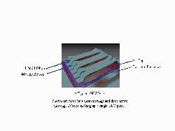
This drawing shows a typical grating light valve display pixel, which features three bias (non-moving) and three active (moving) ribbons.
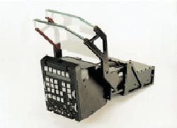
Designers at Flight Visions Inc. are building a small, light, inexpensive head-up display to replace a cathode ray tube display in the B-52 bomber. They are looking at AMLCD, digital light processing (DLP), and grating light valve (GLV), and lasers.
Grating light valve technology — better known as GLV — creates a high-resolution, cost-effective image, and eliminates borders around the images. Designers build GLV arrays using very few components, and with a conventional CMOS process.
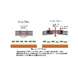
The grating light valve technology involves alternate rows of ribbons, which pull down one-quarter wavelength to create diffraction effects on incident light. It uses reflection and diffraction to create dark and bright image areas.
