Measures designers can take to avoid encapsulant inconsistencies in commercial off-the-shelf electronics
By Tom Adams
ELK GROVE VILLAGE, Ill. – The origins of field failures in plastic-packaged integrated circuits (ICs) can be very subtle. One example: a board assembler receives a new shipment of an IC that he uses regularly. In appearance, design, and electrical performance, the components in this lot are identical to those in preceding lots. Maintaining consistency is particularly important for commercial off-the-shelf (COTS) components upgrades.
There is one minor variation that easily can escape notice: one lot may use an encapsulant that differs from the encapsulate used in recent lots of the same component, which can lead to encapsulant inconsistencies. Its physical appearance is identical to the components in earlier lots, but its responses to the various stresses encountered in reflow, handling, mounting, and other operations may be different.
The assembler may glance at the part number, note their visual appearance, and, assuming that all is well, approve the shipment for assembly. Still, its unknown response stresses may cause unanticipated structural and electrical failures in service.
It is possible that the visually identical but structurally different component will acquire no consequential structural anomaly from these stresses and will provide a normal service life without failure. This is a substantial risk to take, but it can be avoided by acoustically sampling the components from an incoming lot to characterize their mold compound.
Acoustic micro imaging test and measurement tools are the keys to locating, imaging, and analyzing structural anomalies nondestructively within components. The ultrasonic pulses they launch into a component can image the internal structures and analyze their interfaces.
Ultrasonic pulses, however, also can characterize a component’s mold compound without imaging structures or internal defects. Two non-imaging acoustic tests are useful in determining that the current lot and the incoming lot of a given component have identical mold compounds. These tests measure a material’s acoustic Impedance and acoustic attenuation.
Measuring acoustic impedance
Acoustic impedance is a product of the material’s density (in g/cc) and the material’s acoustic velocity (in m/sec) and is measured in units known as MegaRayls. Mold compounds typically possess MegaRayl values between 3.0 and 7.0.
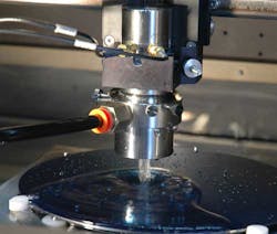
When an assembler receives a new component shipment, the acoustic impedance can be measured by a simple brief test administered by an acoustic micro imaging tool such as those in the C-SAM series from Nordson SONOSCAN. The tool uses a scanning transducer that sends a pulse of ultrasound downward through a 3-millimeter water column into the component.
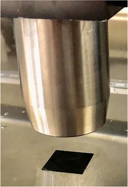
The transducer might be only a few millimeters above the component, and there is a column of water to carry the pulse from the transducer to the component.
In operation, a transducer might be only a few millimeters above the component, and there is a column of water to carry the pulse from the transducer to the component. When a pulse is launched, a portion of the pulse crosses the interface between the water and the top of the component package into the mold compound, while another portion is reflected back to the transducer. The portion returned to the transducer relates to the encapsulant’s density and acoustic velocity. Calculating the encapsulant’s Acoustic Impedance value is simplified by the fact that the corresponding values of the other material at the interface -- water -- are well known.
If the plastic IC package is from a new shipment of a device already in use, the historic average acoustic impedance for the part’s mold compound will also be known.
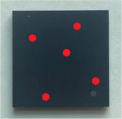
Testing fires pulses near its center and at locations near each corner.
Sample IC packages are selected from the incoming lot. A single pulse is fired into the component at a location near its center and at a location near each corner. The five locations are approximate, not fixed. The component edges, mold marks, and printed areas are avoided. The acoustic impedance values at the five locations where echoes are collected will vary from each other to some degree simply because of the irregular distribution of filler particles.
The five values collected are averaged. The units of measurement are MegaRayls. If these five sites give an average of 5.3, and the historic average is 5.18, it is likely that the mold compound on the device under test is identical to the mold compound used on previous shipments.
If the average of values for the incoming component is 3.6, however, the material is clearly different and testing must be carried out to identify and avoid the conditions that will generate or amplify internal structural problems.
Measuring acoustic attenuation
As a pulse of ultrasound travels through any solid material, to some degree it is scattered and absorbed. The degree of signal lost per unit of distance is used to quantify the acoustic attenuation of a given material.
Measurement is straightforward: the transducer sends a pulse into the top surface of the encapsulant. The pulse travels through it, being attenuated as it goes, to the next material interface (the die, perhaps) and is partly reflected and partly transmitted at the interface. Note that transmission across the interface will remove some energy; the amount can easily be calculated from the density and acoustic velocity of the two materials. The reflected echo travels back through the encapsulant, being attenuated once more, to the transducer for collection. From the data collected is calculated the decibel loss per millimeter of travel through the mold compound.
The decibel loss will depend in part on the frequency of the pulse. Ultrasonic imaging frequencies for electronic components typically range from 15 MHz to 300 MHz and even 400 MHz. Lower frequencies have much more penetration but lower resolution. Higher frequencies produce higher resolution but have limited penetration. A 400 MHz transducer, for example, may give very high resolution of solder bumps through a silicon die not covered by mold compound. Most mold compounds are made of particle-filed polymers, very attenuating materials that require low-frequency ultrasound to penetrate.
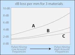
This drawing shows that sample A is a mold compound having fairly high attenuation.
A low frequency ultrasonic pulse, 15 MHz, for example, will travel through the material with relatively small energy losses of perhaps 2 to 3 decibels per millimeter. But higher frequency pulses, represented at the right portion of line A, will be attenuated at a rate around 8 decibels per millimeter.
Materials B and C attenuate low frequency pulses very similarly, but this difference widens as frequencies rise. At high frequencies Material B is significantly more attenuating that Material C.
Benefit of two measurements
The value in measuring acoustic impedance and acoustic attenuation is greater than at first it might appear. Relatively few mold compounds have impedance and attenuation values that are close to the values of another mold compound. Acoustic impedance and attenuation are independent properties of a material and do not necessary relate each other. Performing both measurements makes it easier to know whether a different mold compound has been substituted to package an incoming lot of components.
Any package may have its own weak points -- a bond between two materials that is weak and prone to delamination, for example, or susceptibility to warping. If these limitations are known, the processes the package is going through may be modified to limit or avoid damage. But if a changed mold compound is not suspected, subtle changes may occur during assembly. A bond that is weak but that has not yet separated to become a delamination will not be visible acoustically because the solid-to-air interface of the delamination does not yet exist -- only its potential.
Tom Adams is a consultant for the Sonoscan Inc. division of Nordson Corp. in Elk Grove Village, Ill. Sonoscan specializes in acoustic microscopy and acoustic micro imaging for nondestructive internal inspection and analysis. Contact the company online at www.nordson.com/en/divisions/sonoscan.


