How materials handle higher-power directed-energy weapons
Key Highlights
- Materials for directed-energy weapons must withstand high temperatures, thermal gradients, and repeated thermal cycling without degrading performance.
- Ceramic-based materials like silicon carbide and silicon nitride are promising candidates due to their thermal and electromagnetic properties, but manufacturing scale-up remains challenging.
- Laser and RF systems impose different material requirements, with lasers needing optical transparency and RF systems requiring electromagnetic transmission at longer wavelengths.
- Component performance depends not only on material properties but also on manufacturing quality, interface integrity, and environmental protection measures.
- Active cooling, protective coatings, and advanced joining techniques are critical to maintaining material integrity and electromagnetic performance in operational environments.

NASHUA, N.H. — As military developers increase the power and operating time of directed-energy weapons, components such as lenses, optical windows and radomes have to withstand higher temperatures and thermal stress without interfering with the energy passing through them.
The requirements differ between high-energy lasers and high-power RF systems. Lasers send optical energy through components before the beam leaves the weapon, while RF systems rely on materials that can transmit electromagnetic energy at much longer wavelengths.
“There are just not that many viable material options,” Dr. Shay Harrison, CEO of Free Form Fibers (FFF), told Military & Aerospace Electronics. “The differentiating factor is the ability to transmit signals at that elevated temperature over the desired wavelength range.”
Those conditions can gradually change how a material behaves, affecting both its strength and its ability to transmit energy as intended. Engineers have to find materials that can continue performing under those conditions without interfering with the energy the weapon is designed to deliver.
More power brings more heat
The Air Force Research Laboratory has called heat a major bottleneck in deploying both laser and high-power microwave weapons. Waste heat affects whether components can continue operating and also how much power, cooling equipment, size and weight the overall system requires.
At the material level, however, temperature alone does not tell engineers whether a component will work. The way heat moves through the component and builds up during operation matters as well. For example, a component may not heat uniformly. One area can absorb more energy than another, producing a thermal gradient across the material. Different portions then expand by different amounts, which creates internal stresses even if the component never reaches a temperature that would immediately destroy it.
Duration also changes the conditions a material experiences. A component exposed to a short test does not necessarily experience the same stresses as one supporting repeated engagements. For a laser, some systems operate continuously during an engagement, while others use pulses. RF directed-energy systems can likewise operate with different pulse characteristics and duty cycles.
“These materials are ceramic-based and therefore have the same performance considerations based on energy introduction rate, duration of energy transmission, and effective temperature reached during operation—all of which correlate to the usage profile of near-continuous versus pulsed radiation generation and operation. Thermal shock, creep (deformation and microstructural changes due to thermal-induced stresses), and thermal cycling-driven fatigue are the material behaviors that become primary concerns,” Harrison said.
The time between operating periods matters as well because it determines how much heat the component can shed before the next cycle.
A temperature rating only tells part of the story
Engineers evaluating a material for a directed-energy component cannot rely on a maximum operating temperature alone. The conditions leading up to that temperature, how long the material remains there and what happens as it heats and cools can all affect its performance.
“The application specifications that impact material performance are the ultimate use temperature achieved during operation, thermal gradients through the components during cyclic operation that can lead to thermal-induced stresses, cumulative duration (time) of operation at the elevated temperature and wavelength of the EM signal being used,” Harrison said.
The material itself can also change during that exposure. Harrison said high temperatures can cause “diffusion-driven reorganization of its atomic structure,” with effects on mechanical strength, dielectric properties and thermal conductivity.
Those changes do not necessarily happen at the same rate or produce an immediate mechanical failure. A component may remain intact while its properties gradually move away from the values engineers measured when the material was initially selected. For a structural component, changes in strength may determine whether it can continue carrying a load. For a window or radome, changes in dielectric or optical behavior can affect how electromagnetic energy passes through it.
The energy still has to get through
Ceramics are natural candidates for components exposed to severe thermal and mechanical conditions. Harrison pointed to transition metal carbides, diborides and nitrides such as silicon carbide as materials “well suited for thermomechanical applications.”
A material's electromagnetic properties affect how much energy it transmits, absorbs or reflects at a particular wavelength. That means a ceramic can retain its strength at high temperature and still be unsuitable for a directed-energy component if too much of the required energy is lost as it passes through.
“Broadly speaking, ceramics offer extreme performance capabilities but that comes at a cost of more manufacturing difficulties compared to traditional metals and polymers/plastics,” Harrison noted.
The number of candidate materials shrinks when engineers combine those electromagnetic requirements with the temperatures a directed-energy component may experience. Harrison pointed to silica and silicon nitride as examples of ceramics used where electromagnetic transmission matters, although the appropriate material depends on the wavelength and operating conditions.
Those requirements have to be considered together because improving one property does not necessarily improve another. A material may offer the temperature capability engineers need without providing the required transmission at the weapon's operating wavelength. Its electromagnetic behavior can also change as its temperature rises during operation.

Engineers are therefore selecting for several properties at once rather than looking for the ceramic with the highest temperature rating.
Lasers and RF systems ask different things of materials
High-energy lasers and high-power RF weapons are both directed-energy systems, but they place different demands on materials.
High-energy lasers produce narrow beams, usually in the infrared to visible portion of the electromagnetic spectrum. High-power microwave systems operate at longer wavelengths and can spread energy across a larger area.
“A significant difference between RF and directed-energy laser systems centers on the inherent EM radiation characteristics,” Harrison said. “The shortest wavelengths for RF systems are typically several hundred microns, whereas directed-energy laser systems are primarily in the near-IR, so around 1 micron.”

Transparency depends on wavelength. A material may allow electromagnetic energy in one part of the spectrum to pass through with relatively little loss while absorbing or reflecting more energy at another wavelength. So, engineers have to consider the specific operating range of the weapon rather than treating transparency as a general property of the material.
The components also perform different jobs. An optical window has to allow a concentrated laser beam to pass through without significantly changing its path or quality. An RF-transparent structure may protect or surround an antenna while allowing energy at the system's operating frequencies to pass through.
A window can survive and still hurt the beam
For laser systems in particular, mechanical survival is only part of the job. A window can remain physically intact and still interfere with weapon performance if heat changes how light travels through it. Some of the laser energy passing through an optical component will be absorbed rather than transmitted. That absorbed energy becomes heat.
How much energy the material absorbs matters because a high-energy laser depends on concentrating energy onto a small area of a target. The optical components along that path have to transmit the beam while introducing as little loss and distortion as possible.
If the temperature changes unevenly across an optic, its properties can change unevenly as well. Expansion can also alter its physical shape. Either effect can change the optical path through the material and distort the beam emerging on the other side.
That distortion does not require the window to crack or visibly fail. As power increases, even a little absorption can become more consequential because more energy is available to become heat inside the optic.
“As we continue to push the envelope on performance, with increasing operating temperatures and energy density, the potential for degradation increases,” Harrison said. “The thermal load on the various focusing and transmission elements, such as lenses and windows, from the pulses of source radiation can drive failure mechanisms.”
Naval Research Laboratory work on transparent spinel for high-energy laser windows examined the combination of optical transmission, strength and thermal behavior needed at the weapon's exit aperture. Low optical absorption was important because energy absorbed by the window contributes to heating rather than continuing through it as part of the beam.
ONR has also identified thermal distortion as an area of high-energy laser research and has investigated cooling approaches for optical components. One approach uses controlled microchannels to remove heat near an optic and limit the temperature differences that can distort the beam.
Why ceramic composites are difficult to scale
Silicon nitride offers one example of how engineers try to combine thermal, electromagnetic and mechanical requirements in the same material system.
“Silicon nitride is a desired material for RF applications because it can operate at elevated temperatures (nominally above 1500C) and importantly combined with beneficial dielectric properties (good transmission) in the Gigahertz range of frequencies,” Harrison said.
“Silicon nitride fibers are the crucial reinforcement phase needed to be able to form ceramic matrix composite (CMC) structures. CMCs are critical material systems because they deliver mechanical toughness/resilience compared to more brittle monolithic ceramic components. This resilience, referred to as fracture toughness, allows a CMC to better manage thermal cycling, thermal shock, and mechanical loading, such as vibration or particulate impingement on the component surface,” he continued.
Reinforcing fibers can help prevent cracks from spreading through the surrounding ceramic. In some silicon nitride composites, both the matrix and the reinforcing fibers are made from silicon nitride.
Producing those materials consistently becomes more difficult as the component gets larger and its geometry becomes more complex. Materials research often begins with relatively small, simple samples, while an operational component may be curved or large enough to cover other equipment.
FFF has been developing silicon nitride fibers using laser-driven chemical vapor deposition and is working on a related process for forming the ceramic matrix around those fibers.
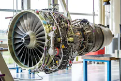
Harrison stated that matrix formation is where “scale up challenges arise in moving from simple demonstration coupons made in the laboratory to more complex geometries,” including components with significant thickness or non-planar shapes.
The matrix has to form around the reinforcing fibers without introducing flaws that undermine the properties engineers are trying to achieve.
“Manufacturing reliability/repeatability are crucial accomplishments that need to be addressed to produce CMC components that perform as expected,” Harrison said. He pointed to air bubbles in the matrix as one example of a flaw that can reduce the effective dielectric behavior of the finished component.
The reinforcing fibers can introduce another manufacturing step. Harrison said some CMC systems require coatings on individual fibers to produce the desired behavior between the fiber and the surrounding matrix. Manufacturers then have to control the thickness and quality of that coating while still maintaining the rest of the composite structure.
That adds another variable as manufacturers move from laboratory samples to larger components. A process that produces the intended properties in a small coupon has to maintain the same fiber distribution, matrix quality and coating characteristics throughout the finished part. For a component that also has to transmit electromagnetic energy, inconsistencies can affect more than its mechanical performance.
The interface can become part of the materials problem
Manufacturing a ceramic component does not end with producing the material itself. Large or complex systems may require separate pieces to be joined, coated or connected to surrounding structures, and those interfaces have to withstand many of the same conditions as the base material.
Ceramics make that particularly difficult because manufacturers cannot rely on many of the processes developed for metals.
“Joining ceramic-based materials is a 50+ year old problem,” Harrison said. “Ceramics do not melt, which means the thousands of years of human experience with metal casting and forging is not applicable.”
Some ceramic joining approaches introduce a secondary material between the pieces being connected. That material can become the limiting part of the assembly if it cannot tolerate the same temperatures as the ceramic around it.
Harrison said existing solutions “generally introduce secondary materials with lower performance (operating temperature capability) compared to the base ceramic materials.” He described ceramic joining as an active area of research.
FFF is pursuing one approach through embedded wire chemical vapor deposition, or EWCVD. Harrison said the company uses the process to form ceramic joints “with no performance-limiting contaminants.”
The finished component still depends on joints that can withstand the same operating conditions as the surrounding ceramic.
The environment adds stresses the laboratory cannot ignore
Even a component that survives the weapon's own thermal load still has to survive its operating environment. Vibration, mechanical shock, moisture and airborne contaminants can all affect materials over time. A useful parallel already exists in commercial aviation.
When teams evaluated silicon carbide-based CMCs for turbine-engine applications, airborne particles such as sand and volcanic ash created problems for the materials protecting the composites. Deposits could melt or chemically interact with those materials, contributing to pitting and erosion. Engineers have developed multilayer environmental barrier coatings to better protect the underlying ceramic from those conditions.
“Significant brainpower and effort have been devoted to devising material-focused engineered solutions,” Harrison said. “In effect, a multi-layer materials sandwich was developed with upwards of a dozen layers of different chemistries and functions.”
Similar protective approaches can address other forms of exposure. “Coatings or intentional compositional additions can be imparted to the component to slow down or strategically react with incoming moisture or oxygen, thus blunting the chemical attack,” he continued. Mechanical solutions can also help isolate materials from vibration and shock.
Directed-energy components face an additional constraint because any protection also has to preserve their electromagnetic performance. A coating that keeps moisture or oxygen away from a ceramic cannot introduce unacceptable absorption or otherwise interfere with the wavelength passing through the component. A mechanical solution intended to isolate vibration cannot distort the structure enough to affect optical or RF performance.
“Ultimately, EM performance is paramount for these materials,” Harrison said. “All the techniques and tools mentioned above are about trying to make sure that the theoretical properties of the material are realized in an actual use environment.”
ONR's high-energy laser research includes aperture coating toughness, optical performance under aero-thermal conditions and thermal distortion.
Cooling becomes a platform problem
Engineers do not expect materials to handle every thermal load passively. How they manage that heat can involve changes both to the material itself and to the system around it.
“Thermal/energy management is one of the biggest challenges facing materials development as systems move to higher levels of performance,” Harrison said. “As operating temperatures and energy densities increase, the risk of performance failure due to material degradation mechanisms greatly increases.”
He notes that engineers can address some of those limitations through cooling and material design.
“These thermomechanical limitations can be addressed through engineering, including active cooling systems deployed to the elements or utilization of composite material systems, and/or compositional variation, via the balance of thermal behavior with electromagnetic transmission performance through chemical formulations,” Harrison said. “The greatest challenge is maintaining the dielectric behavior (EM wavelength-specific transmission properties) which puts serious limits on the range of possible materials that can be utilized.”
Pumps, heat exchangers, coolant and associated equipment consume space, add weight and can require additional electrical power. AFRL has identified heat as one of the major bottlenecks to efficiently deploying directed-energy weapons because of its effects on power consumption and the overall size and weight of the system.
Those constraints become more important when the weapon has to fit aboard a vehicle, aircraft or ship. A ground installation may have room for equipment that would be difficult to accommodate aboard an aircraft or tactical vehicle. Ships can provide more space and electrical generation, but they still have finite power and cooling capacity.
ONR addresses the issue in terms of size, weight, power and cooling, or SWaP-C. Its high-energy laser research includes work on power and beam-director architectures intended to reduce the impact of integrating the weapon onto a naval platform.
The cooling system, materials, power source and other subsystems eventually have to operate together on the platform carrying the weapon. In its 2025 review, GAO reported that early subsystem testing of the Army's 300-kilowatt-class IFPC high-energy laser found integration of associated technologies more complex than anticipated, contributing to extended prototype testing.
A demonstration and a deployable weapon answer different questions
Directed-energy weapons have spent decades moving between laboratories, demonstrations and operational experiments. The military has demonstrated lasers against drones and developed high-power microwave systems for counter-UAS missions. But GAO has found that moving directed-energy prototypes into acquisition programs remains difficult.
Materials engineering is one part of that transition, but a laser also needs power generation, beam control, tracking and thermal management. High-power microwave systems depend on RF sources and other electronics capable of producing and directing the required electromagnetic energy.
For materials engineers, a successful laboratory sample still has to become a full-size component that can be manufactured consistently and integrated with the rest of the weapon.
That changes what engineers need to learn from testing. A laboratory experiment can isolate a material and measure its properties under controlled conditions. A finished component has to perform while attached to surrounding structures, exposed to the weapon's operating cycle and working alongside cooling, power and other subsystems.
The question also shifts from whether one component can meet a requirement to whether manufacturers can reproduce that performance. Manufacturing variations may matter when the finished part depends on tightly controlled optical or dielectric properties. Testing therefore has to account for both the material itself and the way manufacturing turns it into an operational component.