Acoustic time travel for failed electronic components
By Tom Adams
ELK GROVE VILLAGE, Ill. – When electronic components for critical applications experience structural failure in service, it typically is worthwhile to collect as much data as possible about the failures to reduce the risk of similar failures in the future.
The mechanism that caused a structural field failure might have occurred suddenly, or might have been the result of gradual change. If the component itself has largely survived, it may be imaged by ultrasound via an acoustic micro imaging tool to view and analyze its current internal structure to help determine the cause of the failure.
In some applications test and measurement that involves post-damage acoustic imaging is not possible because the component was destroyed, or because it is irretrievable, as in many space applications. But if advance precautions have been taken, something else can be done: the entire imageable volume of the component in its original state before installation, and before failure, can be examined and recorded acoustically.
The imaging mode is called the Virtual Rescanning Mode, or VRM, and is performed by the Nordson SONOSCAN line of C-SAM acoustic micro imaging tools. This unusual technique can find small or oddly located anomalies that may have later changed their dimensions and caused the failure.
Ordinary acoustic screening of components, whether they are loose and arranged on trays or already mounted, typically collects return echoes only from a specific depth of interest, and not from the whole thickness of the component.
Related: Achieving reliability with lead-free solders
In a flip chip, this depth will likely be the zone between the die face and the substrate to incorporate the solder bumps and the underfill. In a BGA package, the depths of interest could include both surfaces of the die, from just above the die face to the substrate. The most frequently used imaging mode is C-mode, which measures the amplitude of each of thousands of arriving echoes per second and applies a pixel color to each echo depending on its amplitude and polarity. The emphasis is on high throughput and on finding known defect types in expected locations.
To scan critical components whose original configuration will be of value if a structural failure occurs in service, VRM typically uses the same C-mode approach as high-throughput scanning, but differs in that it collects and stores every echo from every depth in the entire acoustically accessible volume of the component.
The data is stored as a large matrix file. If the critical component does not fail, the matrix file may never be accessed. But if the component does fail, and cannot itself be imaged, the matrix file permits traveling through time to the component’s original state, as recorded in precise acoustic detail. Two aspects of the matrix file are important:
If the matrix file is imaged with the same imaging parameters (depth, gating, frequency, etc.) that were used to image the physical component, the images of the physical component and the image of the virtual component will be identical. New users of VRM sometimes expect to see some subtle difference, but there is none, because the same echoes are being imaged. The matrix file is an exact copy of all of the echoes from all of the echo-producing interfaces in the component in its original state.
In addition to guiding the user about possible causes of a field failure, VRM may tell whether the structural anomaly that caused the failure existed in the component as received from the manufacturer, or whether it was caused by later processing.
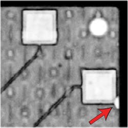
Figure 1 is the acoustic image of a small portion of a Micro BGA, and was made from the VRM matrix file of echoes collected before the component failed. The image is gated and focused on the interface between the substrate and the mold compound at the top of the substrate.
The red arrow points out a tiny delamination between the mold compound and the substrate. It is bright white because it is filled with air. This gap between the substrate and the mold compound may be only a small fraction of a micron thick. At the top of the gap, the interface between the air and the mold compound reflects virtually all of the acoustic energy delivered by the pulse. No ultrasound crosses the interface to go deeper.
Delaminations are dangerous because they tend to grow laterally. If they are positioned between two solids having different rates of thermal expansion, frequent thermal changes make it possible for the delamination to grow and break a conducting element in the component. In this component, imaging of the matrix file revealed additional delaminations elsewhere in the component, and suggested that more thorough inspection for delaminations might be needed.
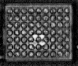
Figure 2 is the VRM image of a tiny flip chip that later failed. The bright regions near the center are air bubbles in the underfill, into which portions of one or more solder balls could have flowed until the ball collapsed sufficiently to break the electrical connection.
Related: Military and aerospace companies ensure electronic systems with test and measurement tools
To image the matrix file of this component in VRM, the C-SAM’S thin-slice mode was used. In this mode, returning echoes are collected from each x-y location at several or many gates during a single scan. A gate defines the upper and lower limits of a horizontal slice within the component. Return echoes whose arrival time, measured in nanoseconds, indicates that they originated from a material interface within a gate are collected and used to make an acoustic image of the slice of the component that lies within that particular gate. A gate can be as narrow vertically as a few nanoseconds, although they are generally much wider in time.
In this case the gate extended downward at least to the top of the substrate. The white features near the center of the image represent the very strong reflection of pulsed ultrasound from the air-to-underfill interface. The original high-throughput acoustic scan of the physical component had only a single gate and apparently did not reach deep enough to image these anomalies. The somewhat narrower (vertically) gate used to image the VRM matrix file revealed the anomalies in their original positions.
Because VRM has available all the echoes from the component in its original state, and because it can use any of the 15 or so imaging modes, the user has at hand a very large number of precise ways of imaging a particular component. The various imaging modes use combinations of the echo’s arrival time, frequency, polarity and amplitude to create acoustic images. During in-house electrical testing of components, where thermal and structural stresses are known, the method can provide more precise recommendations for preventing similar failures.
But if a component has failed in circumstances that render it irretrievable, the versatility of the VRM module comes into play. The entire volume of the component as represented in the matrix file can be imaged by any of the 15 available imaging modes. And each mode can be used in multiple frequencies and gains. The chances that a meaningful anomaly can remain hidden for long in the matrix file are slim.
