Materials for Antenna Design: New Possibilities Enable Rugged, Cost-Effective Designs
Materials for Antenna Design: New Possibilities Enable Rugged, Cost-Effective Designs
Kathleen Fasenfest
Senior Electrical Engineer, Antenna Products
TE Connectivity (TE) Aerospace Defense & Marine
As devices, platforms and budgets shrink, demand is increasing for smaller, lighter weight antennas. For aerospace and defense applications, traditional antenna materials – printed circuit boards, machined aluminum enclosures, and thermoset radomes – offer tried and true but costly approaches for building antennas. A new approach is needed to meet next-generation antenna requirements.
The expanding consumer wireless industry has fueled rapid advances in injection molding and selective metallization technologies. Wireless antennas have swiftly evolved from printed circuit board and stamped metal designs to molded parts metallized with conductive inks. The high-volume manufacture of wireless antennas has quickly matured these technologies for the consumer market.
The aerospace and defense industries can benefit from this technological maturity. Key materials advances for aerospace and defense include injection molding of composites as well as selective metallization processes. These technologies offer paths for creating compact three-dimensional antenna geometries, saving space and weight, minimizing part count, and even reducing aerodynamic drag for flight applications. These advances in materials science combine to allow cost-effective realization of 3D antenna designs that are mechanically robust and can withstand harsh environmental conditions.
Some consumer-grade technology is poorly suited to the harsh environments and stringent RF requirements associated with aerospace and defense. For selecting technologies to transition from the consumer market to aerospace and defense, the three main goals are:
1. Rugged. The antenna materials must withstand vibration, mechanical shock, temperature and weather extremes without physical or RF degradation. Unlike antennas in “throwaway” consumer devices, they should last decades.
2. Low Loss. Since energy should be transmitted and received efficiently—without the losses that increase heat and degrade sensitivity—low-loss metallization and substrates are required.
3. Cost Effective. The main goal here is materials and processes that allow volume manufacturing with repeatable precision and no defects or rework. Higher levels of component integration can reduce part counts and installation times.
Traditional Methods: Effective But Not Efficient
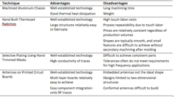
Machined aluminum parts and hand layups of radomes certainly yield effective antennas, but fabrication methods can be costly. Selective plating, for example, typically involves hand-trimmed masks that make it difficult to maintain the tight tolerances required for high-frequency applications. Similarly, thermoset radomes not only have a high labor content, but often require secondary machining to achieve small features.
Antennas are commonly etched onto printed circuit boards (PCBs). PCB antennas allow easy fabrication through proven processes, and sometimes can be integrated with matching circuits and other components on the same board. The main drawback is that these antennas are limited to 2D structures. Two-dimensional antennas do not efficiently use all the available space within an enclosure. The resulting antenna may be electrically shorter than desirable to maximize gain and bandwidth.
Figure 1 summarizes the strengths and weakness of traditional approaches to antenna manufacturing.
New Technologies: Efficient Production and Effective Capabilities
Recent advances in materials and fabrication technologies are now enabling improved antenna designs with reduced size and weight, high integration, and lower costs. Key innovations influencing next-generation antenna designs include composite materials and selective metallization processes. These innovations combine to allow cost-effective realization of 3D antennas that are mechanically robust and can withstand harsh environmental conditions.
Composite Substrates
A new generation of composite materials offer two main benefits:
1. The materials can be tailored to specific application needs by careful selection of fillers; and
2. The materials are injection moldable, with the ability to create intricate and precise shapes with high repeatability.
The fillers are the secret sauce that permit custom properties to be achieved. Fillers include carbon fibers, glass fibers, hollow microspheres, graphene, carbon nanotubes, and foaming agents. Among the critical antenna properties that can be adjusted by careful application of fillers are:
Dielectric Properties. Glass fibers increase the dielectric constant of most composites, enabling antenna size reduction when these composites are used as substrate materials. Composite materials can also be engineered to provide “designer” dielectric constants through the addition of various filling materials, such as hollow glass microspheres, conductive particles or foaming agents.
Loss Tangent. A high loss tangent offers absorptive properties, and control of the loss tangent allows tailoring of RF absorption. Conductive-fiber fillers can absorb energy radiated in unwanted directions. This can increase antenna gain in the desired direction through decreasing interference. The same direction-specific absorption can be used to shield electronics near antennas.
Weight Savings. Conductive composites typically offer a 30 to 40 percent weight savings over aluminum parts. Carbon fiber composites may also be sturdier than aluminum counterparts because they are not easily dented or deformed and are not susceptible to corrosion.
High Conductivity. Carbon-fiber composites are addressing the need for lightweight, cost-effective, mass-producible electrically conductive parts to achieve ground planes or EMI protection. For antenna applications, uses of carbon fiber composites range from ground planes to enclosures.
3D Selective Metallization
As mentioned above, the traditional approach to metallization requires labor-intensive application of physical masks to the part’s surface followed by a multi-step plating process. Because of its high labor content, selectively metallized parts are usually relatively expensive.
TE Connectivity (TE) is one of the largest providers of embedded antennas for consumer applications. Our consumer antenna heritage brings us well-established solutions for cost-effective selective metallization of three-dimensional parts. Key processes include laser direct structuring (LDS) and conductive coatings. Both selective metallization processes can repeatedly achieve traces and fine structures as small as 100 μm. These processes are suitable for creating three-dimensional antennas and traces on molded parts.
Laser Direct Structuring (LDS) is a three-step process.
• The substrate is molded in a standard thermoplastic molding process.
• A laser then etches the part to expose a specialized plating additive in the polymer resin.
• The substrate is placed in an electroless nickel plating bath, where the plating adheres only to the plastic that has been activated by the laser.
No mold or mask redesign is required to change the metallization pattern. A quick update to the laser path allows modification of the artwork design. LDS also provides the ability to create 3D circuits, such as 3D RF couplers and direct circuit (DC) connections to other devices.
Conductive Coatings. Conductive coatings allow cost-effective metallization of arbitrary materials—including composites—for creating conformal antennas on nearly any shape. These 3D selective metallization processes can be applied to a wide range of substrates – including plastics, chemically resistant composites, glass, ceramic, and metals – with acceptable adhesion, a temperature range from -75°C to +260°C, and corrosion resistance.
High-quality conductive coatings are durable enough to withstand shock, vibration, fluids, and salt spray to the levels typically required for aerospace and defense applications. Conductive coatings are compatible with molded or machined parts, so the same process can be used for low-volume prototyping and production.
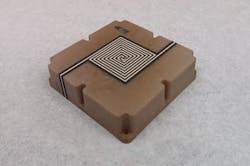
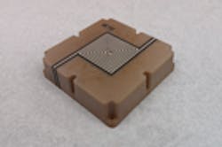
Figure 1. Conductive coatings can be flexibly and precisely applied to composite substrates. (Source: TE Connectivity)
Application to Antennas
Composites offer a great approach for building moldable, mass producible, inexpensive antenna substrates. These substrates can have arbitrary shapes and even include mechanical mounting provisions such as retention ledges and snap features for easy assembly. This technology offers the antenna engineer design flexibility not afforded by traditional substrate materials.
Composites and selective metallization allow higher levels of antenna integration. The aerospace industry, for example, is developing a highly modular approach to decentralized avionics known as the Mini-MRP (Modular Rack Principle). One type of module is a wire access point for in-flight entertainment systems. A composite enclosure, like the one in Figure 2, can not only include an embedded antenna, but connector shells, shielding, and other features.
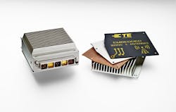
Figure 2. Antennas can be embedded into composite enclosures (Source: TE Connectivity)
Selective metallization through conductive coatings offers a good solution for creating circuit traces on composite parts which would more typically be etched using standard circuit board techniques. The conductivity of some conductive coatings can approach the conductivity of bulk copper, adding only minimal loss to the circuit while enabling more cost-effective manufacturing. However, this selective metallization process particularly excels when applied to the manufacture of three-dimensional circuit topologies. Three dimensional RF couplers and direct circuit connections to antennas now become realizable through this technology.
Within the antenna assemblies, aluminum parts can account for a large portion of the total assembly weight. Composite ground planes offer 30 to 40 percent weight savings over traditional aluminum parts, with high manufacturability and often significant potential cost savings. Composite ground planes can be conductively coated if necessary to provide improved electromagnetic interference (EMI) shielding, grounding, or lightning strike protection performance. Compared to the original aluminum parts that require significant machining time to fabricate, composite ground planes can be quite cost-competitive.
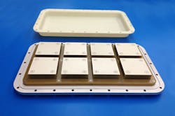
Figure 3. Modular antenna array, which exhibits wide use of composite materials and conductive coatings in its construction. (Source: TE Connectivity)
Traditional radome manufacturing involves hand layups of multiple material layers—a tedious, slow and costly process that becomes difficult when intricate radome shapes are required. Recent advances in long glass fiber and continuous glass fiber composites offer approaches for achieving thinner, lighter-weight radomes using injection molding. The ability to mold strong, lightweight radomes represents a significant change in the economics of antenna design and fabrication. When required, 3D selective metallization can provide lightning diversion or frequency selectivity features to these radomes.
The Future of Antennas Has Arrived
Conductive coatings and composites enable cost-effective manufacture of novel antennas with reduced size, weight, and cost. Injection molded composites offer an excellent approach for mass producing antenna substrates and radomes. Selective metallization with conductive coatings allows the creation of three-dimensional antennas, circuit traces, and ground plane structures. These processes combine to offer electrically and mechanically robust antennas and arrays in conformal, lightweight form factors. These advances in materials, processes and technology enable the size and weight reductions required for next-generation antenna designs.
We recently sat down with Kathleen to ask her a few more questions regarding the newest technologies for antenna design. Click here to see the Q&A.
Click here to learn more about TE’s standard and custom antenna solutions.
